Instructions, Regulator 1, Regulator 2 – Basler Electric AVC63-7F User Manual
Page 4: Regulator 3, Avc63-7f
Publication
9302800994
Revision
D
Instructions
Date
03/12
Page
4 of 4
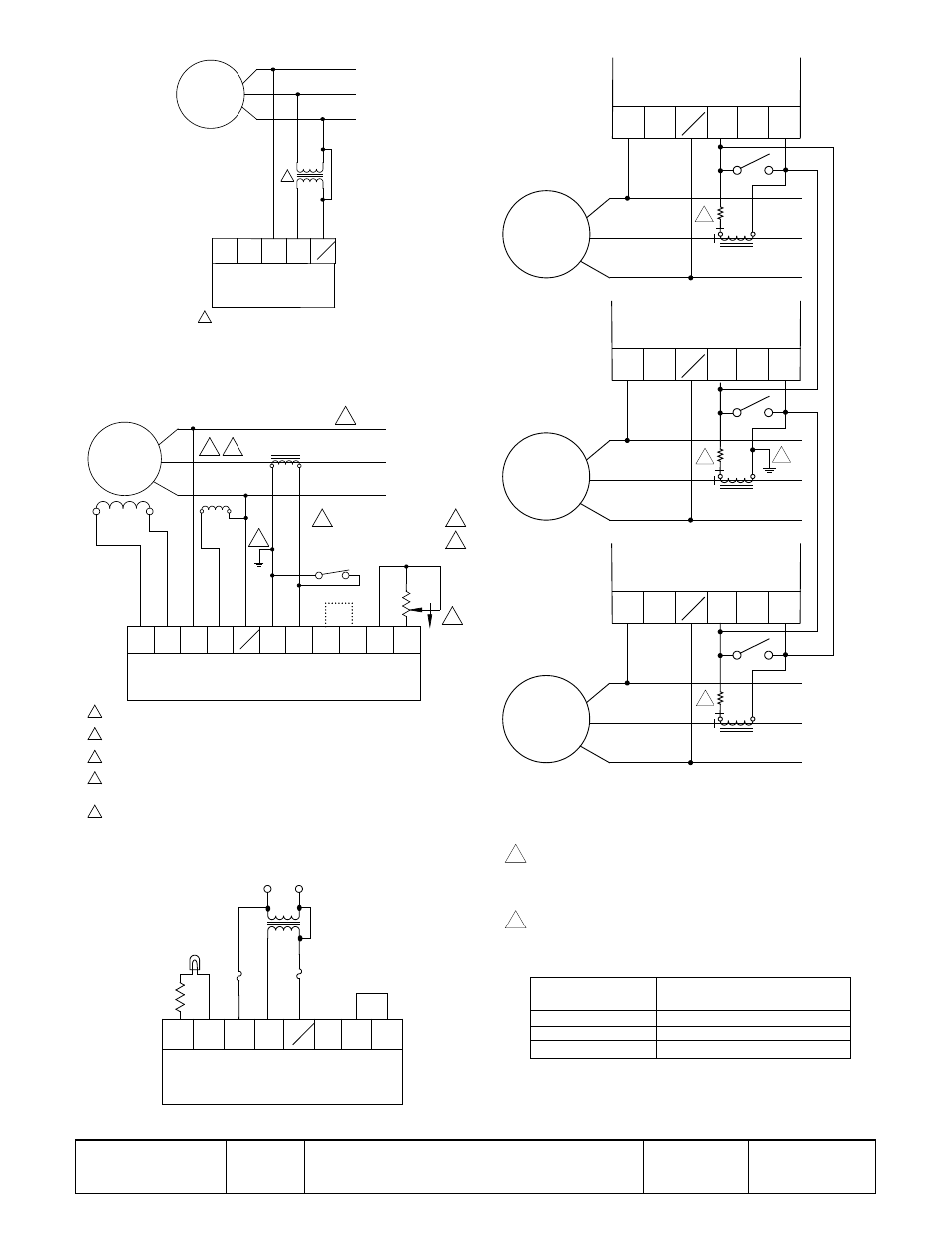
Figure 4. Typical Shunt-Pow ered Interconnection
(Delta Connection)
Note: This is a partial drawing of Figure 3.
Figure 5. Typical Auxiliary Winding Pow ered Interconnection
Figure 7. Operational Test
Figure 6. Reactive Differential (Cross Current) Compensation
CT Interconnection
A
B
C
E1
3
AVC63-7F
P0029-04
03-01-05
GENERATOR
480 Vac L-L
(277 Vac L-N)
50/60 HZ
4
E3
480 VAC
240 VAC
Item not supplied by Basler Electric Co.
1
1
A
B
C
FIELD
EXCITER
OPEN TO PARALLEL
CLOSE FOR SINGLE UNIT
UNIT/PARALLEL SWITCH
RHEOSTAT
VOLT. ADJ.
REMOTE
1.5K
2W
CW
7
6
COM
50
E1
2
1
3
F+
F-
AVC63-7F
P0029-02
03-20-12
GENERATOR
400 - 480 VAC
50/60 HZ
3
4
E3
5A SEC NOMINAL
PARALLELING CT
TO LOAD
OR
CIRCUIT
BREAKER
4
2
2
2
1
1
1
2
3
4
AUXILIARY
WINDING
5
5
Phase rotation A-B-C.
Item not supplied by Basler Electric Co.
If remote voltage adjust is not used, short terminals 6 and 7 together.
Short terminals 50 and COM together for 50 Hz operation. Leave unconnected for 60 Hz
operation.
The secondary winding of a sensing transformer must be grounded as closely to the
transformer as practical. When interconnecting more than one transformer, ensure that
the secondary winding of only one transformer is grounded.
10 OHM
10 WATT
LIGHT BULB
120 V
240 VAC
7
6
3
E1
F+
F-
AVC63-7F
P0029-03
03-01-05
4
E3
480 VAC
NOTES
1. When more than three generators are to be paralleled,
continue connections as shown.
2. Paralleling CT polarities are shown with ABC phase rotation.
When connected in cross-current, external resistors may be
required to improve reactive load sharing among generators using
regulators with dissimilar current input burdens. Use the following
table as a guide.
The secondary winding of a sensing transformer must be
grounded as closely to the transformer as practical. When
interconnecting more than one transformer, ensure that the
secondary winding of only one transformer is grounded.
3
A
B
C
GENERATOR
1
CT
E1
2
1
Regulator 1
4
E3
A
B
C
GENERATOR
2
CT
E1
2
1
Regulator 2
4
E3
A
B
C
GENERATOR
3
CT
E1
2
1
Regulator 3
4
E3
3
3
3
P
00
04
-2
3
03
-1
4-
12
4
4
Voltage Regulator
CT Burden
2.5 VA
10 VA
25 VA
External Resistor Value
(not considering lead length)
Not required
0.3 ohms, 15 W
0.9 ohms, 50 W