Instructions, Avc63-7f – Basler Electric AVC63-7F User Manual
Page 3
Publication
9302800994
Revision
D
Instructions
Date
03/12
Page
3 of 4
1. Installation of a jumper across terminals 6 and 7 allows
the internal (front panel) VOLT adjustment to vary the
generator nominal voltage over the range shown in the
Specifications.
Voltage Adjustment
2. A 1,500 ohm, 2 watt rheostat may be connected to
terminals 6 and 7. This will allow approximately ±10%
adjustment via the remote, 1,500 ohm rheostat.
The droop adjustment allows for adjustment of the amount
of droop, which will occur in the generator output voltage
for a given amount of reactive load current. A CT should be
selected which will supply the AVC with 3 to 5 amperes of
current with rated load and power factor on the generator.
With 5 amperes of current supplied by the CT, at 0.8 power
factor, the amount of droop can be adjusted from 0 to 6%
of nominal generator voltage.
Droop Adjustment
1. Determine the amount of droop desired; 3% to 5% is
common. Adjust the droop potentiometer fully CCW.
2. Bring the generator up to rated speed and rated
voltage. Apply full load at rated power factor.
3. Adjust the droop potentiometer until the desired
amount of droop is achieved.
OPERATIONAL TEST
To operationally test any AVC 63-7F, refer to Figure 7 and
perform the following steps.
1. Connect the voltage regulator as shown in Figure 7
and apply 240 Vac.
2. Adjust the front panel VOLT control fully counter-
clockwise (CCW).
Result: Observe that the lamp does not light.
3. Adjust the front panel VOLT control fully clockwise
(CW).
Result: Observe that the lamp is now lit.
4. Adjust the front panel VOLT control until the lamp just
goes out.
Regulator operation is satisfactory if the above results are
obtained. Stability, however, must be tested with the
generator and regulator operating.
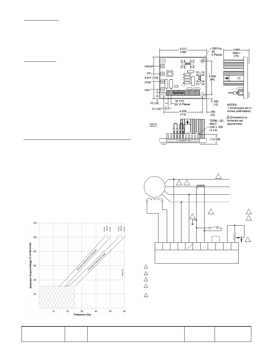
Figure 1. Typical AVC63-7F Frequency Compensation Curves
Figure 2. AVC63-7F Dimensions
Figure 3. Typical Shunt-Pow ered Interconnection
(Wye Connection)
A
B
C
FIELD
EXCITER
OPEN TO PARALLEL
CLOSE FOR SINGLE UNIT
UNIT/PARALLEL SWITCH
RHEOSTAT
VOLT. ADJ.
REMOTE
1.5K
2W
CW
7
6
COM
50
E1
2
1
3
F+
F-
AVC63-7F
P0029-01
03-20-12
GENERATOR
480 Vac L-L
(277 Vac L-N)
50/60 HZ
3
4
E3
5A SEC NOMINAL
PARALLELING CT
TO LOAD
OR
CIRCUIT
BREAKER
4
2
2
2
1
1
1
2
3
4
N
5
5
Phase rotation A-B-C.
Item not supplied by Basler Electric Co.
If remote voltage adjust is not used, short terminals 6 and 7 together.
Short terminals 50 and COM together for 50 Hz operation. Leave unconnected for 60 Hz
operation.
The secondary winding of a sensing transformer must be grounded as closely to the
transformer as practical. When interconnecting more than one transformer, ensure that
the secondary winding of only one transformer is grounded.