Instructions, Avc63-7, Regulator 1 – Basler Electric AVC63-7 User Manual
Page 4: Regulator 2, Regulator 3, 4 of 4
Publication
9302800991
Revision
B
Instructions
Date
03/12
Page
4 of 4
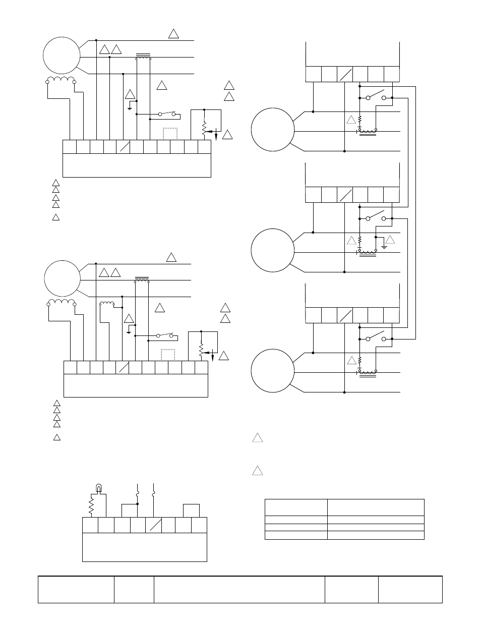
Figure 3. Interconnections, Typical Shunt-Pow ered
Figure 4. Interconnections, Typical Auxiliary Winding Pow ered
Figure 6. Interconnections, Operational Test
Figure 5. Interconnections, Reactive Differential (Cross-
Current) Compensation
A
B
C
FIELD
EXCITER
OPEN TO PARALLEL
CLOSE FOR SINGLE UNIT
UNIT/PARALLEL SWITCH
RHEOSTAT
VOLT. ADJ.
REMOTE
1.5K
2W
CW
7
6
COM
50
E1
2
1
3
F+
F-
AVC63-7
P0004-21.vsd
03-14-12
GENERATOR
200 - 240 VAC
50/60 HZ
3
4
E3
5A SEC NOMINAL
PARALLELING CT
TO LOAD
OR
CIRCUIT
BREAKER
4
2
2
2
1
1
1
2
3
4
Phase rotation A-B-C.
Item not supplied by Basler Electric Co.
If remote voltage adjust is not used, short terminals 6 and 7 together.
Short terminals 50 and COM together for 50 Hz operation. Leave unconnected for
60 Hz operation.
5
The secondary winding of a sensing transformer must be grounded as closely to
the transformer as practical. When interconnecting more than one transformer,
ensure that the secondary winding of only one transformer is grounded.
5
A
B
C
FIELD
EXCITER
OPEN TO PARALLEL
CLOSE FOR SINGLE UNIT
UNIT/PARALLEL SWITCH
RHEOSTAT
VOLT. ADJ.
REMOTE
1.5K
2W
CW
7
6
COM
50
E1
2
1
3
F+
F-
AVC63-7
P0004-22.vsd
03-14-12
GENERATOR
200 - 240 VAC
50/60 HZ
3
4
E3
5A SEC NOMINAL
PARALLELING CT
TO LOAD
OR
CIRCUIT
BREAKER
4
2
2
2
1
1
1
2
3
4
Phase rotation A-B-C.
Item not supplied by Basler Electric Co.
If remote voltage adjust is not used, short terminals 6 and 7 together.
Short terminals 50 and COM together for 50 Hz operation. Leave unconnected for
60 Hz operation.
AUXILIARY
WINDING
5
The secondary winding of a sensing transformer must be grounded as closely to the
transformer as practical. When interconnecting more than one transformer, ensure
that the secondary winding of only one transformer is grounded.
5
10 OHM
10 WATT
LIGHT BULB
120 V
240 VAC
7
6
E1
3
F+
F-
AVC63-7
P0004-24
02-10-05
4
E3
NOTES
1. When more than three generators are to be paralleled,
continue connections as shown.
2. Paralleling CT polarities are shown with ABC phase rotation.
When connected in cross-current, external resistors may be
required to improve reactive load sharing among generators using
regulators with dissimilar current input burdens. Use the following
table as a guide.
The secondary winding of a sensing transformer must be
grounded as closely to the transformer as practical. When
interconnecting more than one transformer, ensure that the
secondary winding of only one transformer is grounded.
3
A
B
C
GENERATOR
1
CT
E1
2
1
Regulator 1
4
E3
A
B
C
GENERATOR
2
CT
E1
2
1
Regulator 2
4
E3
A
B
C
GENERATOR
3
CT
E1
2
1
Regulator 3
4
E3
3
3
3
P
00
04
-2
3
03
-1
4-
12
4
4
Voltage Regulator
CT Burden
2.5 VA
10 VA
25 VA
External Resistor Value
(not considering lead length)
Not required
0.3 ohms, 15 W
0.9 ohms, 50 W