Instructions – Basler Electric AVC63-7 User Manual
Page 3
Publication
9302800991
Revision
B
Instructions
Date
03/12
Page
3 of 4
2. Rotation of the front panel STAB control in the
counterclockwise (CCW) direction will speed response
time. If rotated too far CCW, the generator voltage may
oscillate (hunt).
3. Rotate the front panel STAB control CCW until the
system starts oscillating and then rotate CW just past
the point where oscillation occurred.
1. Installation of a jumper across terminals 6 and 7 allows
the internal (front panel) VOLT adjustment to vary the
generator nominal voltage over the range shown in the
Specifications.
Voltage Adjustment
2. A 1,500 ohm, 2 watt rheostat may be connected to
terminals 6 and 7. This will allow approximately +10%
adjustment via the remote 1,500 ohm rheostat.
The droop adjustment allows for adjustment of the amount
of droop which will occur in the generator output voltage for
a given amount of reactive load current. A CT should be
selected which will supply the AVC with 3 to 5 amperes of
current with rated load and power factor on the generator.
With 5 amperes of current supplied by the CT, at 0.8 power
factor, the amount of droop can be adjusted from 0 to 6% of
nominal generator voltage.
Droop Adjustment
1. Determine the amount of droop desired; 3% to 5% is
common. Adjust the droop potentiometer fully CCW.
2. Bring the generator up to rated speed and rated
voltage. Apply full load at rated power factor.
3. Adjust the droop potentiometer until the desired amount
of droop is achieved.
OPERATIONAL TEST
To operationally test any AVC 63-7, refer to Figure 6 and
perform the following steps.
1. Connect the voltage regulator as shown in Figure 6 and
apply 240 Vac.
2. Adjust the front panel VOLT control fully
counterclockwise (CCW).
RESULT: Observe that the lamp does not light.
3. Adjust the front panel VOLT control fully clockwise
(CW).
RESULT: Observe that the lamp is now lit.
4. Adjust the front panel VOLT control until the lamp just
goes out.
Regulator operation is satisfactory if the above results are
obtained. Stability, however, must be tested with the
generator and regulator operating.
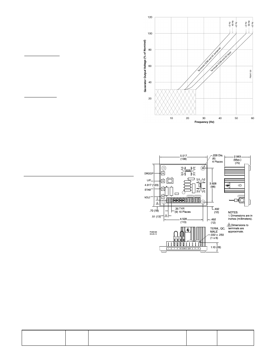
Figure 1. Typical AVC63-7 Frequency Compensation Curves
Figure 2. AVC63-7 Dimensions