Control panel (display) – Avery Dennison ALX 924 Operating Manual User Manual
Page 7
09/06 Rev. 3.06-01
OPERATING MANUAL
Device Description
ALX 92x
7
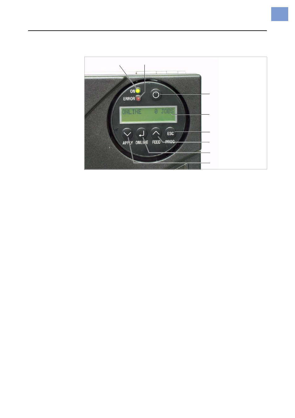
Control panel (display)
[5] ALX 92x control panel.
Power indicator
Lights up green, when the device is switched on.
Error indicator
Lights up red, when the device is in message mode.
Display
With 32 digits and two lines, the display shows the operating conditions
(modes) for parameters, values, status and errors. You can select the lan-
guage you want to use for the display. Backlighting ensures good legibility.
Button functions
The buttons offer a multitude of operating functions. A logical menu structure
is used for operation. The meaning of each button varies according to the op-
erating mode and the menu item. Additionally, special functions have been
programmed for certain button combinations.
Depending on the modes and menu levels, the following functions apply for
each button:
Online button
•
For switching between online and offline mode.
•
For confirming entries, menu items and messages.
•
For selecting print jobs and for entering values in standalone mode.
Apply button
•
Triggers the application process. Requirements:
– Applicator fitted and activated
– Device offline.
•
Also for accessing deeper levels within the menu structure and selecting
menu items.
•
For decrementing values.
Feed button
•
For feeding in material when the device is offline.
•
For starting the printing process once the feed has been stopped (in online
mode).
•
Also for accessing deeper levels within the menu structure and selecting
menu items.
•
Increments values.
Prog button
•
For accessing the parameter menu when offline.
Display
Power indicator
Error indicator
On-off switch
Prog button
Feed button
Online button
Apply button