Nstallation, Cont, Acceptable vent configurations restrictor position – Avalon Firestyles D-V-1995 User Manual
Page 14
P
AGE
14
I
NSTALLATION
(
CONT
.)
Acceptable Vent Configurations
Restrictor Position
¥
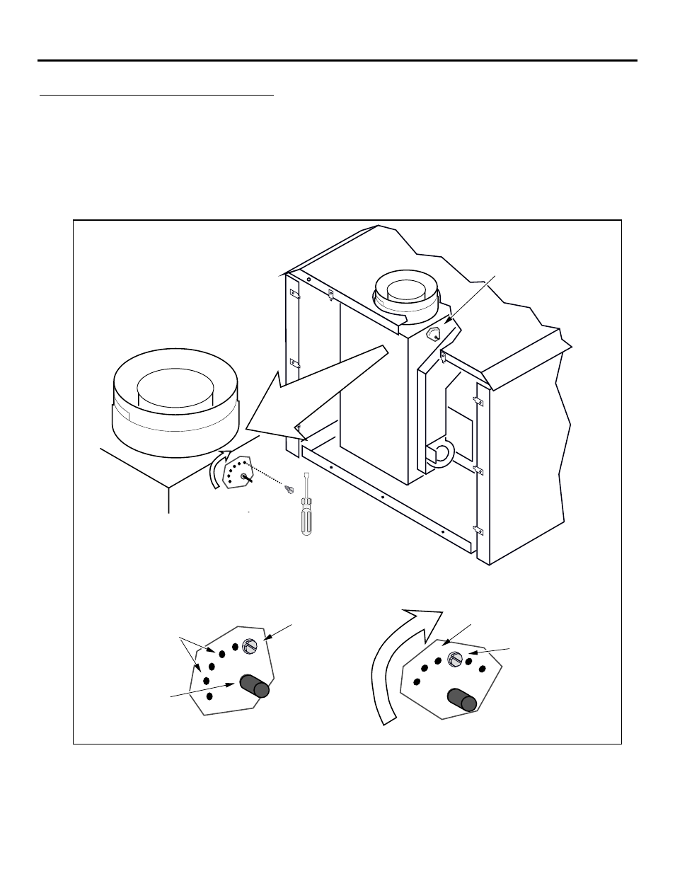
A vent restrictor is built into the appliance to adjust the flow rate of exhaust gases. This insures
proper flames for the wide variety of vent configurations. The restrictor consists of a butterfly valve
below the starter section of pipe and an adjustment plate with index holes used to hold the valve in a
fixed position. Depending upon the vent configuration, you may be required to adjust the restrictor
position. The charts for acceptable vent configurations describe which position the vent restrictor
must be in.
Cutaway view of the back of the stove
with the rear panel removed
Adjustment
Plate
Remove the rear panel. The
adjustment plate is on the right
side (when looking from the rear)
of the starter section of vent.
To Adjust the Restrictor:
To Access the Restrictor:
1/4" Nutdriver
Determine which position the restrictor should be in (see the
charts under "Acceptable Vent Configurations" - the stock position is #1).
Remove the screw with a 1/4" nutdriver (or screwdriver).
Rotate the adjustment plate clockwise until the correct index hole is above the pivot point.
Insert the screw into the correct index hole and tighten.
1
2
3
4
1
2
3
4
5
6
Index Holes
Pivot Point
The six holes on
the restrictor
plate correspond
to the six
restrictor
positions
This
restrictor is
in Position
#3.
Screw
Rotate the adjustment plate to
change the restrictor position.
NOTE: Position #1 is the fully open position