Connection and wiring, Usb-link 2 6 technical guide, Figure 2: usb-link 2 connection & wiring – Auto-Zone Control Systems USB-Link 2 Technical Guide, Installation Instructions for the USB-Link 2 (Version 01E) User Manual
Page 6
USB-Link 2
6
Technical Guide
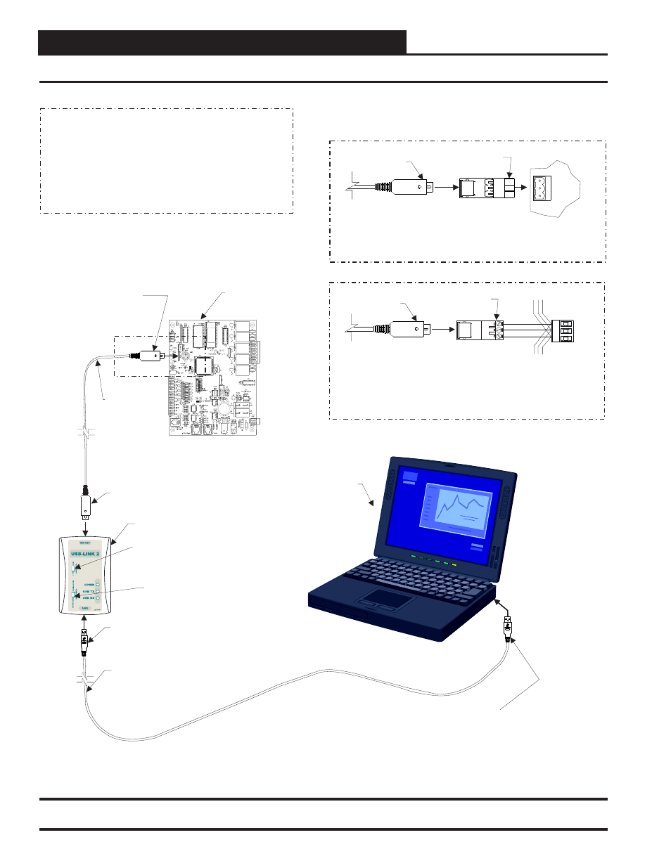
Connection and Wiring
Figure 2: USB-Link 2 Connection & Wiring
Adapter
Supplied With USB-Link 2
PL101904
Adapter
Supplied With USB-Link 2
PL101905
Mini-DIN Cable
Mini-DIN Cable
Use The
Adapter To Plug In To A Terminal Socket And Connect
The USB-Link 2 On Boards That Don’t Have A Female Mini-DIN Plug Connection.
This Only Allows Communications With The Board It Is Connected To
PL101904
NOTE:
.
Use The
Adapter And Wire To A Terminal Block
To Connect The USB-Link 2 To The Local Communications Loop
All Controllers
That Are Connected To The System
P 101905
L
On Boards That Don’t Have A Female Mini-DIN Plug Connection.
This Allows Communications With
. See Note 1.
NOTE:
USB-Link 2
Controller With
Mini-DIN Plug
USB Cable
Supplied With
USB-Link 2
Connect Type A Cable End To
USB Port On Desktop Or Laptop
Personal Computer.
USB Drivers Supplied With The USB-
Link 2 Must Be Installed On Your Computer
Before USB-Link 2 Can Be Used.
NOTE:
Connect Type B Cable End
To USB Port On USB-Link 2.
Connect Mini-DIN Cable End
To Mini-DIN Port On USB-Link.
Configuration Switch
Must Be Set To Stand Alone
Or Network Depending On Your
Installation.
Mini-DIN Cable
Supplied With
USB-Link
Connect The USB-Link 2
Mini D
Cable To The
- IN
Connector On
Controllers That Are Supplied
With Them.
All
Controllers That Are
Connected To The System
- IN
Female
Mini D
Plug
This Allows
Communications With
.
See Note 1.
NOTE:
STAND ALONE
NETWORK
SHLD
SHLD
T
T
R
R
Notes:
1. For Networked Systems, In The Event That Your CommLink II or III
Has An EPROM Software Version Earlier Than 3.15
, You Will Need An
EPROM Upgrade Before You Can View All Controllers On Your System.
In
You Must Disconnect The
Communication Loop From The Controller Your USB-Link Is Plugged
Into
Or Your MiniLink
Has An EPROM Software Version Earlier Than 3.14
See Troubleshooting For More Information.
The Meantime, In O
, S
rder
To View A Single Controller Using Prism II,
et The USB-Link Configuration Switch To Stand Alone, Set The
Type Of CommLink In Prism II To USB Link Stand Alone, And Cycle
Power By Disconnecting And Reconnecting the USB Power Supply Cable.
Communication Speed Switch
Must Be Set To Low or High Speed
Depending on Your Controller’s
Baud Rate.
Computer
With Prism
2 Software
Installed