9 p702 - pch gpio header, 10 j1101 - p2 xmc j16 differential i/o, Table 3-15 – Artesyn iVPX7225 RTM Installation and Use (April 2015) User Manual
Page 43: Table 3-16, P702 - pch gpio header pinout, Table 3-17, J1101 - p2 xmc j16 differential i/o pinout, Controls, leds and connectors
Controls, LEDs and Connectors
iVPX7225 RTM Installation and Use (6806800S35B)
43
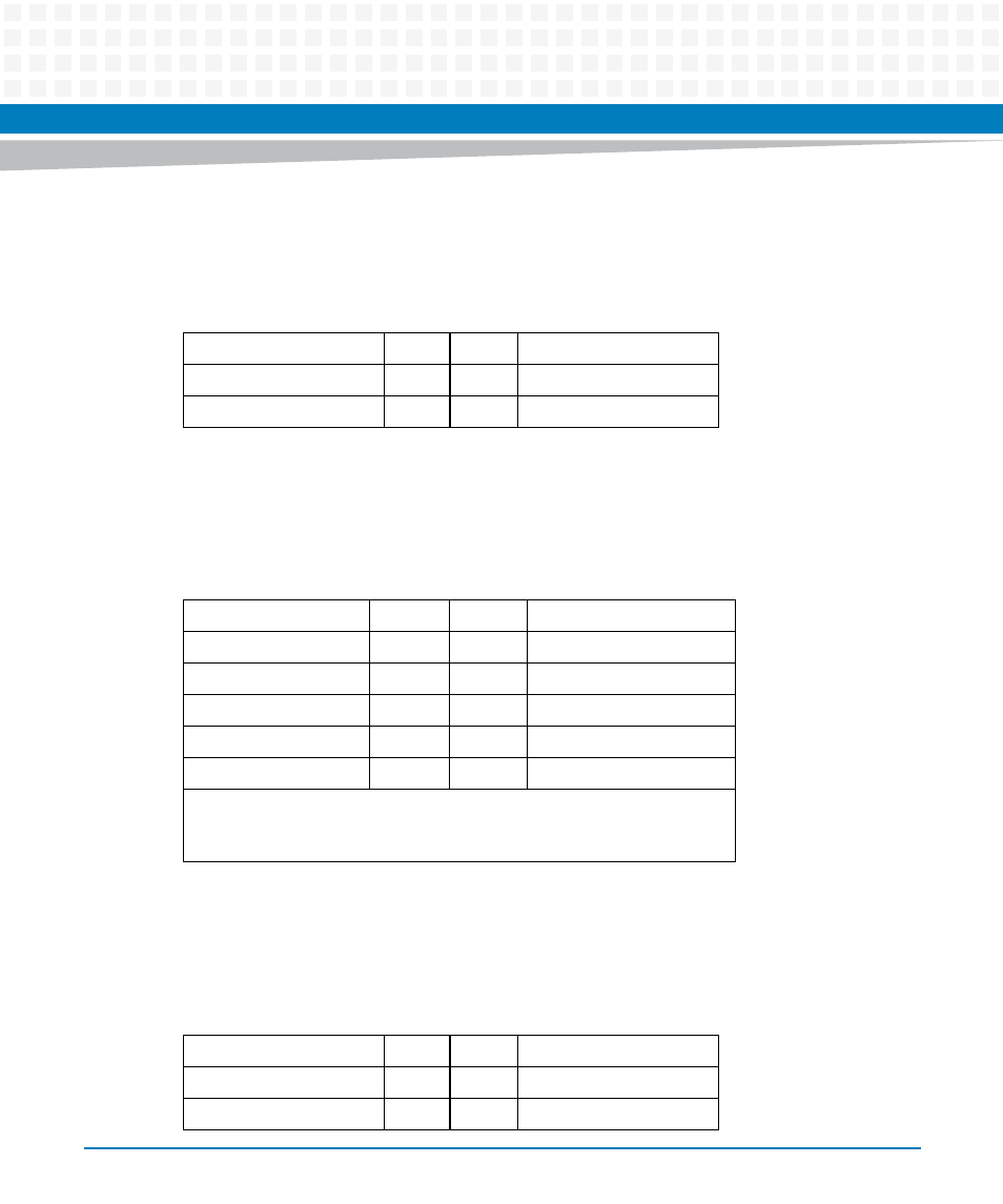
3.6.8
J1201 - IPMC Debug Mini-B USB Physical Receptacle
3.6.9
P702 - PCH GPIO Header
3.6.10 J1101 - P2 XMC J16 Differential I/O
Table 3-15 J1201 – IPMC Debug Mini-B USB Physical Receptacle Pinout
NC
1
2
Rx In
Tx Out
3
4
NC
Ground
5
Table 3-16 P702 - PCH GPIO Header Pinout
Ground
1
2
GPIO1 (PCH GPIO 22)
GPIO0 (PCH GPIO 17)
3
4
GPIO3 (PCH GPIO 7)
GPIO2 (PCH GPIO 6)
5
6
Ground
GPIO4 (PCH GPIO 68)
7
8
GPIO5 (PCH GPIO 69)
Ground
9
10
GPIO7 (PCH GPIO 71)
GPIO6 (PCH GPIO 70)
11
12
Reserved
Refer to the Intel Panther Point External Design Specification for voltage
levels and functionality. Each PCH_GPIO is pulled to +3.3V by a 10KOhm
resistor onboard the iVPX7225.
Table 3-17 J1101 - P2 XMC J16 Differential I/O Pinout
Ground
1
2
Ground
P2 XMC 12D 1 N
3
4
P2 XMC 12D 7 N
P2 XMC 12D 1 P
5
6
P2 XMC 12D 7 P
- ARTM-9405 16x10GbE Installation and Use Guide (May 2014) (64 pages)
- ATCA 7370 / ATCA 7370-S Installation and Use (January 2015) (256 pages)
- ATCA 7370 / ATCA 7370-S Installation and Use (September 2014) (254 pages)
- ARTM-831X Installation and Use (June 2014) (346 pages)
- ATCA-7350 - Integrating with Workbench User Guide (September 2014) (34 pages)
- ATCA-7350 Installation and Use (September 2014) (208 pages)
- ATCA-7365-CE Installation and Use (May 2014) (306 pages)
- ATCA-7365-CE Installation and Use (Jan 2015) (300 pages)
- ATCA-7365-CE Installation and Use (May 2014) (294 pages)
- ATCA-7368 Installation and Use (June 2014) (222 pages)
- ATCA-7475 Installation and Use (October 2014) (284 pages)
- ATCA-7480 Installation and Use (April 2015) (330 pages)
- ATCA-8330 Installation and Use (April 2015) (236 pages)
- ATCA-8320 Installation and Use (May 2014) (456 pages)
- ATCA-9305 User's Manual (May 2014) (270 pages)
- ATCA-9405 Installation and Use (October 2014) (168 pages)
- ATCA-F120 Installation and Use (August 2014) (122 pages)
- ATCA-F140 Installation and Use (September 2014) (138 pages)
- ATCA-MF106 Installation and Use (September 2014) (86 pages)
- Centellis-4440/AXP1440 Installation and Use (September 2014) (208 pages)
- Centellis 4410 (AXP-1410) Installation and Use (July 2014) (202 pages)
- Centellis 2100 Release 3.0 Installation and Use (March 2015) (192 pages)
- Centellis 2100 Release 3.0 Installation and Use (March 2015) (176 pages)
- Centellis 2000 User Card-10GE Installation and Use (May 2014) (54 pages)
- Centellis 2000 User Card-10GE with Telco Alarm Installation and Use (May 2014) (60 pages)
- COMX-CAR-210 Installation and Use (August 2014) (76 pages)
- COMX-P1022 Installation and Use (July 2014) (84 pages)
- COMX-P2020 Installation and Use (February 2015) (100 pages)
- COMX-CORE Series Installation and Use (August 2014) (128 pages)
- COMX-P2020 Installation and Use (July 2014) (100 pages)
- COMX-P4080-2G-ENP2 Installation and Use (August 2014) (70 pages)
- COMX-P4080 Installation and Use (August 2014) (126 pages)
- COMX-P40x0 ENP2 Installation and Use (August 2014) (130 pages)
- COMX-P40x0 ENP2 Installation and Use (January 2015) (140 pages)
- MITX-430/MITX-440-DVI-2E Installation and Use (August 2014) (118 pages)
- CPCI-6200 Installation and Use (May 2015) (234 pages)
- SCP-MITX-CORE-820-SM Installation and Use (August 2014) (132 pages)
- iVPX7225 Installation and Use (April 2015) (168 pages)
- MVME2502 Installation and Use (December 2014) (166 pages)
- MVME2502 Installation and Use (August 2014) (150 pages)
- MVME2500 VxWorks 6.8 AMP User Guide (August 2014) (40 pages)
- MVME2500 VxWorks 6.8 User Guide (April 2014) (44 pages)
- MVME3100 Single Board Computer Installation and Use (June 2014) (156 pages)
- MVME4100 Single Board Computer Installation and Use (June 2014) (136 pages)