Telemetry block, Serial port, Telemetry block 29 serial port 29 – ARRIS TM508 Installation Guide User Manual
Page 39: Patterns: startup sequence, Mta startup sequence, Cm startup sequence
29
TM508/TM512 Installation Guide Release 5 Standard 1.2 Mar 2007
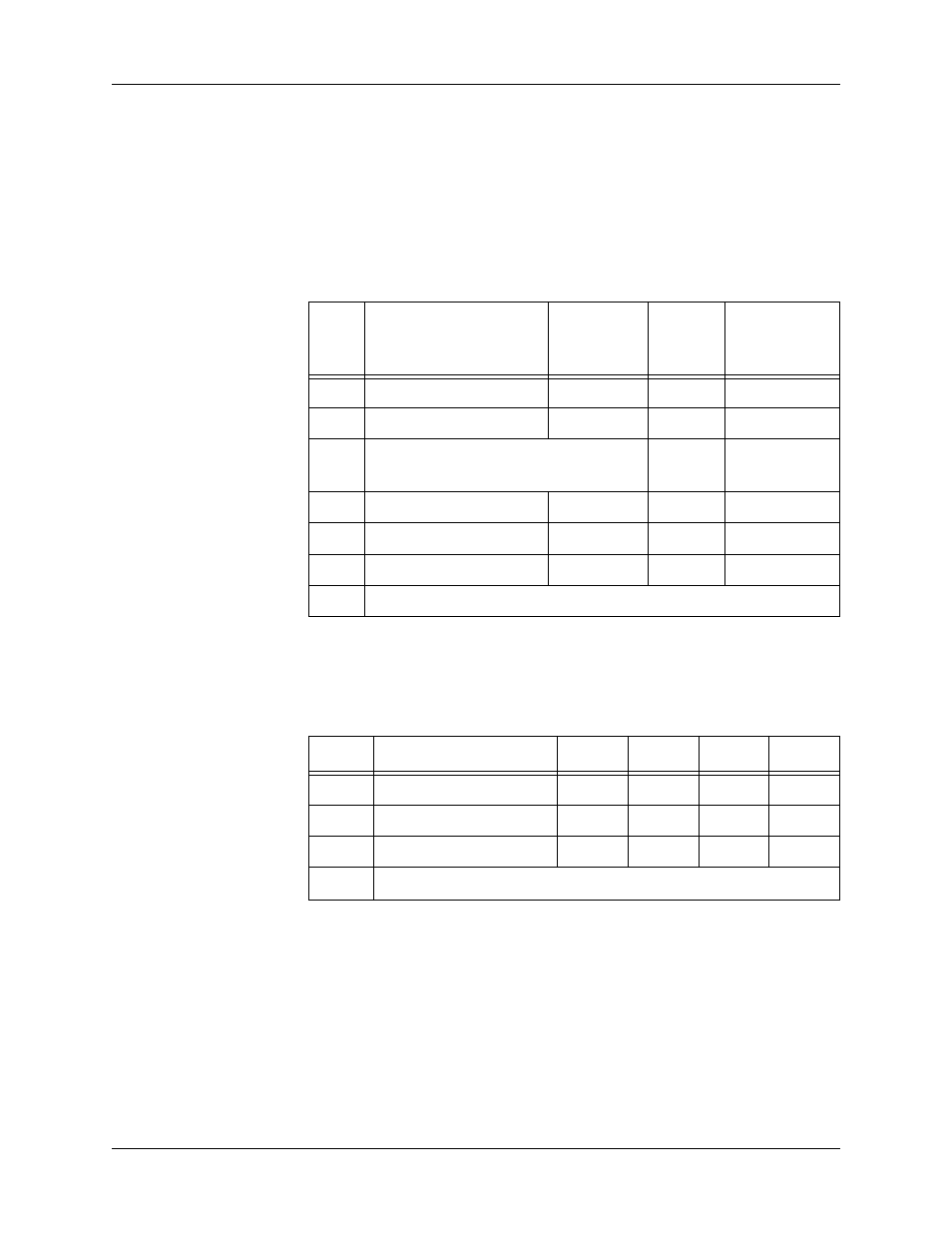
Patterns: Startup Sequence
The following tables show LED patterns for the Telephony Modem
during each phase of the startup sequence.
MTA Startup Sequence
If the MTA fails to complete registration, note the LED pattern and call
your next level of support.
CM Startup Sequence
If the modem fails to complete registration, note the LED pattern and
call your cable operator for assistance.
Telemetry Block
The telemetry block provides an interface between the local power sup-
ply unit (LPSU) status signals and the network management facility.
See “Telemetry Block Pinouts” on page 8 for pinouts and alarm infor-
mation.
Serial Port
Reserved for future use.
Step
Description
Power,
DS, US,
Online
Link
Telephone
0
No Power
Off
Off
Off
1
Self-Test
Flash
Flash
Flash
2-4
CM Initialization; see “
CM Startup
Sequence
” below.
Off
Off
5
Telephony DHCP
On
On
Flash
6
Telephony SNMP/TFTP
On
On Off
7
Telephony RSIP
On
On
Flash
MTA Normal Operation
Step
Description
DS
US
Online
Link
2
Downstream scan/sync
Flash
Off
Off
Off
3
Upstream ranging
On
Flash
Off
Off
4
DOCSIS DHCP/TFTP
On
On
Flash
Off
CM Normal Operation