Analog Way Scan Vision VHX II - VHX480 User Manual
Page 13
SCAN VISION VHX II
™
Chapter 7 : RS-232 PROGRAMMER'S GUIDE
PAGE 13
7-4. COMMANDS AND RESPONSES TABLE
The following table resumes all of the commands which are recognized as valid and the responses that will be returned to
the controlling device.
ASCII
RESPONSE
COMMAND
TYPE
VALUE
COMMAND
DESCRIPTION
MIN MAX
DESCRIPTION
FRONT PANEL COMMANDS
C
CMD
FREEZE.
Rd/Wr
0
65535 0 = unfreeze
1 = freeze.
P
FLICK
Anti-flicker adjustment
Rd/Wr
0
2
0 = level 1
1 = level 2
2 = level 3
G
HPOS
Horizontal position.
Rd/Wr
0
255
H
VPOS
Vertical position.
Rd/Wr
0
255
I
HSIZE
Horizontal size.
Rd/Wr
0
255
J
VSIZE
Vertical size.
Rd/Wr
0
255
K
ZHPOS
Horizontal position (in zoom mode).
Rd/Wr
0
255
L
ZVPOS
Vertical zoom position (in zoom mode) Rd/Wr
0
255
M
ZHSIZE
Horizontal size (in zoom mode).
Rd/Wr
0
255
N
ZVSIZE
Vertical size (in zoom mode).
Rd/Wr
0
255
O
TSO
Zoom mode selection.
Rd/Wr
0
255 Please see value description (next section).
STATUS COMMANDS
?
DEV
Device type.
Rd
65535 18 = VHX480.
@
UNIT
Measures unity
Rd
0
65535
D
DHI
Input line frequency.
Rd
Please see value description (next section).
E
GRT
Input frame frequency.
Rd
Please see value description (next section).
F
TSY
Input format.
Rd
Please see value description (next section).
A
VERM
Firmware version.
Rd
0
65535
B
VERR
Firmware version.
Rd
0
65535
7-5. VALUES DESCRIPTION
Values sent or received are in decimal. Depending on the command letter, the value can be used as a linear control (ex :
255I to set the horizontal size to the maximum) or as a set of bits (ex : F command with multiple controls). In this case, the
value must be converted in binary base to understand every bit action.
EXAMPLE : The controlling device receives the message TSY71 (F command)
Decimal value 71 = Binary value 0100 0111
71 = (128 x 0) + (64 x 1) + (32 x 0) + (16 x 0) + (8 x 0) + (4 x 1) + (2 x 1) + (1 x 1)
bit 0 = 1 means input signal detected.
bit 1 = 1 means positive H sync detected.
bit 2 = 1 means positive V sync detected.
bit 3, 4, 5 = 000 means H & V Separate sync detected.
bit 6 = 1 means non interlaced input signal detected.
bit 7 = 0 means signal compatible with the input range frequency.
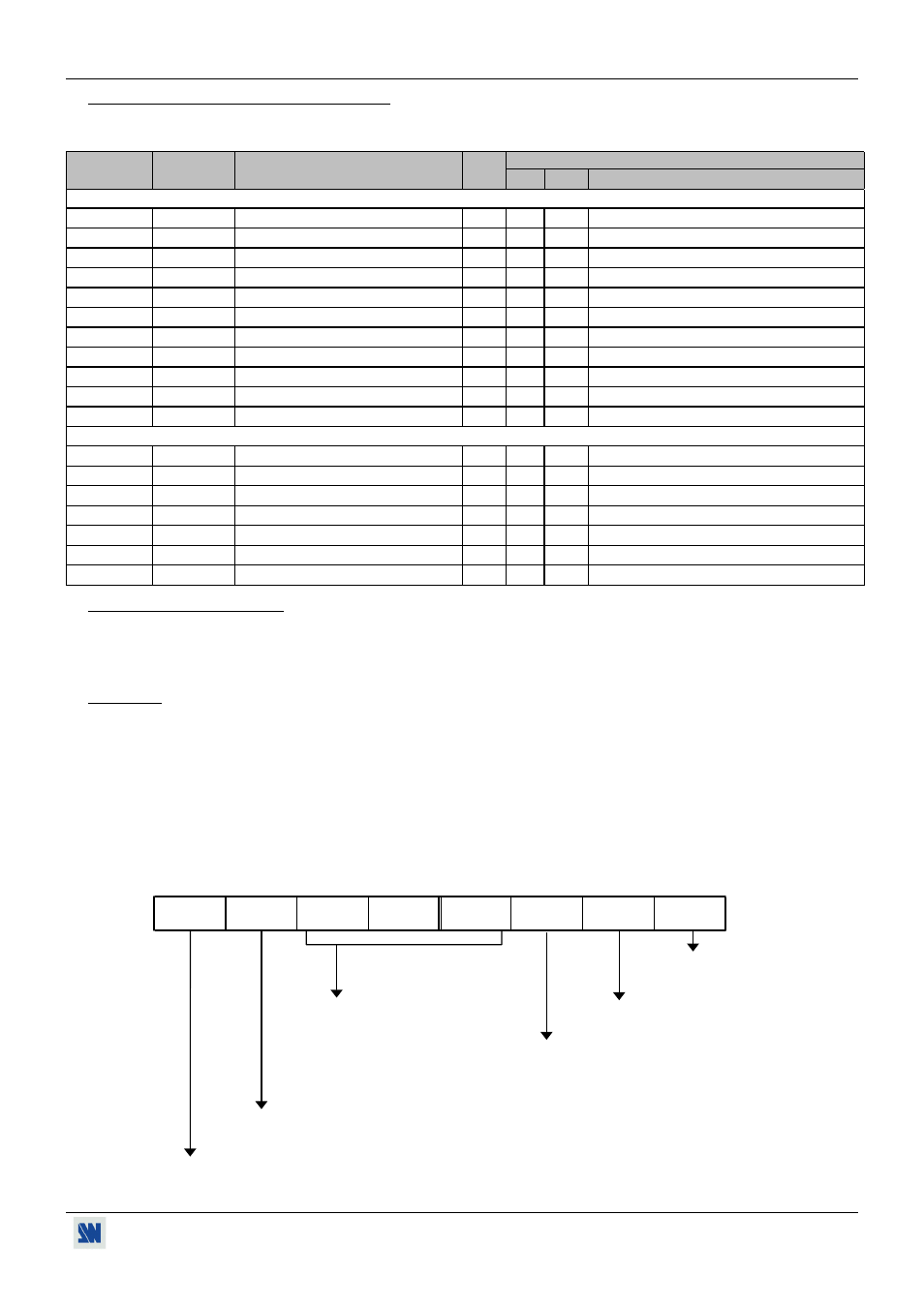
• F command returns the input signal status.
bit 7
(128)
bit 6
(64)
bit 5
(32)
bit 4
(16)
bit 3
(8)
bit 2
(4)
bit 1
(2)
bit 0
(1)
0 = No signal detected.
1 = Signal detected.
xx0 = H&V Separate Sync.
0 = Negative H Sync.
x01 = Sync On Green (SOG).
1 = Positive H Sync.
011 = 1V Composite Sync.
0 = Negative V Sync.
111 = TTL Composite Sync.
1 = Positive V Sync.
0 = Interlaced signal.
1 = Non Interlaced signal.
1 = Signal incompatible with the input range frequency.