Rs-232 data communications port -7, Hardware interface -7, Software interface -7 – AMETEK GUPS 2400A-107 User Manual
Page 25: Table 3, Rs-232 connector pin-out -7, 9 rs-232 data communications port
Operation
GUPS 2400A
–107 Operation Manual
3-7
3.9 RS-232 Data Communications Port
The RS-232 data communications port provides an interface between a data terminal (or a
computer emulating a data terminal) and the GUPS 2400A-107. It allows transfer of information
such as parameter values, mode of operation, and alarm conditions.
3.9.1
Hardware Interface
Interface signals for communication to and from the GUPS 2400A-107 are provided via a
connector (MS3470W12-8S) located on the rear panel of the unit. The RS-232 interface
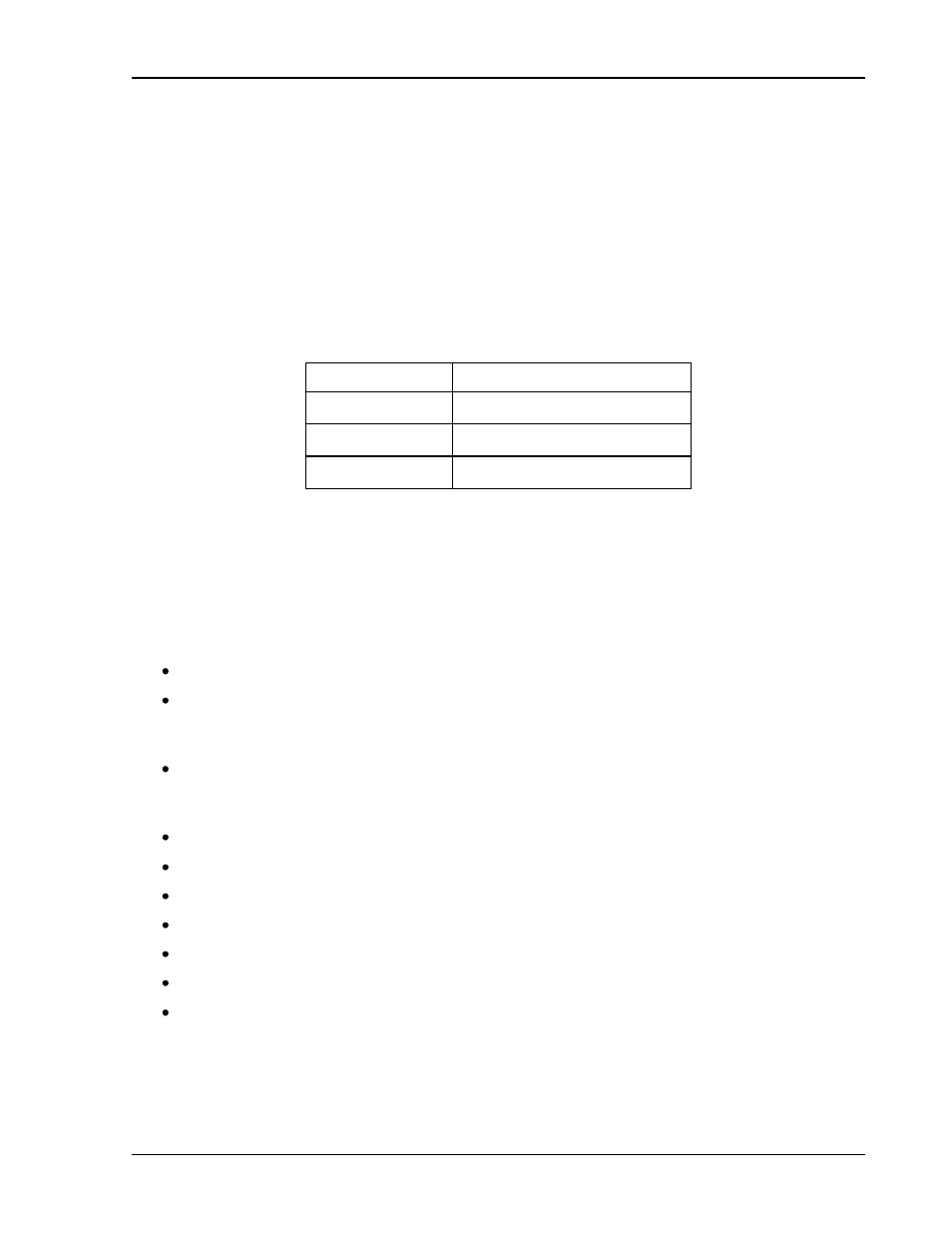
connector is designated as J3, DATA/ALARM PORT. The J3 connector pin-out for the RS-232
interface is given in Table 3
Pin Number
Signal
D
Transmit from the GUPS
E
Receive to the GUPS
F
Signal Ground
Table 3
–3. RS-232 Connector Pin-Out
3.9.2
Software Interface
The RS-232 interface firmware in the GUPS 2400A-107 has the following communication
features:
Two sets of remote terminal software commands
Text data request commands, which are applicable for dumb terminal display of the
unit status. Text data request commands return both descriptive text and the data
values requested
Fast ―data only‖ data request commands called the Elgar Terminal Interface (ETI), for
use by a program running on a host computer. The ETI commands return only the
data values that are requested
Data available via the RS-232 interface includes
AC Line Loss signal
AC Input voltage in floating point or hexadecimal
AC output voltage in floating point or hexadecimal
AC output current in floating point or hexadecimal
Battery/Charger DC voltage in floating point or hexadecimal
Impending shutdown annunciation