Installation -2, Air intake and exhaust -2, Input/output connectors -2 – AMETEK GUPS 2400A-107 User Manual
Page 12: Table 2, Gups 2400a-107 input/output connectors -2, 3 installation, 4 air intake and exhaust, 5 input/output connectors
Installation
2-2
GUPS 2400A
–107 Operation Manual
When returning the instrument to Elgar, suitable shipping containers and packing material must
be used. If the instrument needs to be shipped and proper packing material is not available,
contact Elgar to provide containers and shipping instructions.
2.3 Installation
The Model GUPS 2400A-107 is 7" (178 mm) high and is designed to be installed in a standard
19" (483 mm) wide cabinet enclosure or a transit case.
Refer to Figure 2
–1 through Figure 2–3 for information on outline and mounting dimensions.
2.4 Air Intake and Exhaust
The air intake is located on the front panel of the instrument and the exhaust is through the rear
panel. Care must be taken not to block the air intake and exhaust. No special vertical
separation is required when stacking instruments. However, a 1¾" (44.5 mm) vertical spacer
above and below the instrument may improve cooling.
CAUTION!
Avoid blocking the instrument air intakes or exhaust.
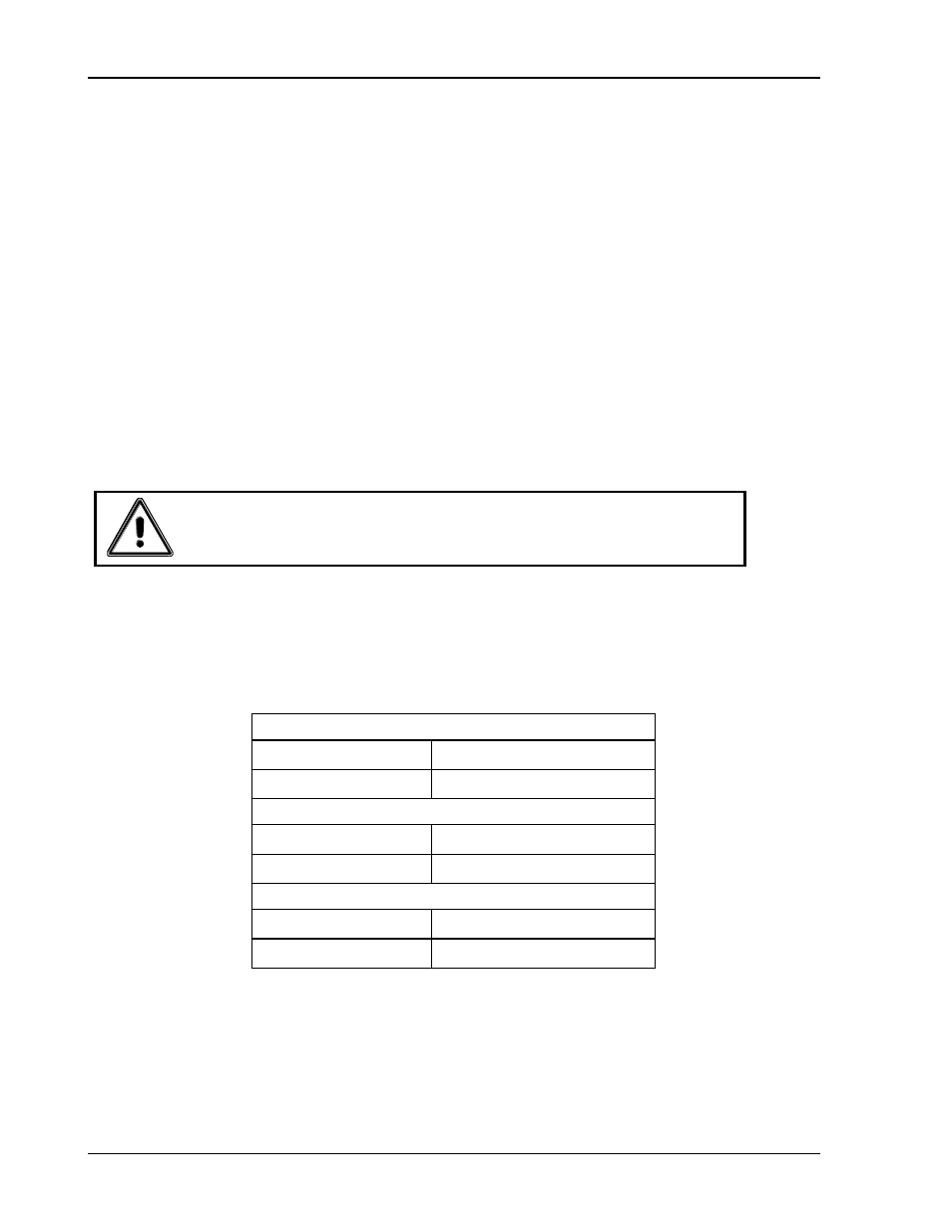
2.5 Input/Output Connectors
–1 provides a listing of the GUPS 2400A-107 input and output connectors.
J1: AC Input Connector
Panel Connector
MS3102E20-4P
Mating Connector
MS3456W20-4S
J2: AC Output Connector
Panel Connector
MS3102E20-19S
Mating Connector
MS3456W20-19P
J3: Data/Alarm Port Connector
Panel Connector
MS3470W12-8S
Mating Connector
MS3476W12-8P
Table 2
–1. GUPS 2400A-107 Input/Output Connectors