Connectors -4, Table 3, Gups 2400a-107 connector pin assignments -4 – AMETEK GUPS 2400A-107 User Manual
Page 22: 6 connectors
Operation
3-4
GUPS 2400A
–107 Operation Manual
If SHUTDOWN is asserted while the AC input is not present and the inverter is running from the
battery, the output relay will open and output power will be turned off; the inverter and control
circuits will also be shut down. After shutdown, the OUTPUT ON switch must be manually
toggled to turn the output back on.
RS-232 TRANSMIT/RECEIVE
RS-232 transmit and receive for data communications. Refer to Section 3.9 for more
information on RS-232 interface.
OUTPUT CURRENT
An AC voltage signal that is proportional to the AC output current. The output is 0.221V/A, or
4.6 VRMS at full load. This signal is transformer isolated from the other control signals.
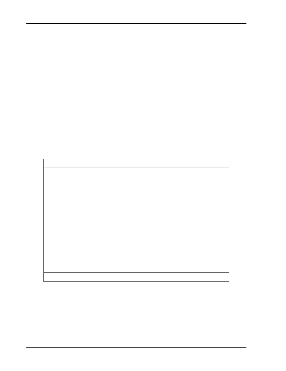
3.6 Connectors
The GUPS 2400A-107 has cylindrical, metal-shell connectors with bayonet coupling for all
input/output connections of power and signal. All connectors are located on the rear panel.
Pin assignments are listed in Table 3
Connector
Pin Assignment
Connector J1,
AC INPUT
Pin A: Phase A
Pin B: Phase B
Pin C: Phase C
Pin D: Chassis Ground
(Neutral not used)
Connector J2,
AC OUTPUT
Pin A: Line
Pin B: Neutral (internally connected to chassis)
Pin C: Chassis Ground
Connector J3,
DATA/ALARM PORT
Pin A: AC FAIL normally-open relay contact
Pin B: LOW BATTERY normally-open relay contact
Pin C: SHUTDOWN input for remote shutdown
Pin D: RS-232 TRANSMIT signal (output)
Pin E: RS-232 RECEIVE signal (input)
Pin F: SIGNAL RETURN for signals on Pins A-E
Pin G: OUTPUT CURRENT sense signal
Pin H: Return for OUTPUT CURRENT sense signal
GROUND STUD
#10-32 Stud: Earth Ground
Table 3
–1. GUPS 2400A-107 Connector Pin Assignments