Remote connect web interface – American Time SiteSync IQ User Manual
Page 37
37
© American Time
Glossary
Appendix
Troubleshooting
Clock
Installation
System Contr
oller
Installation
Intr
oduction
SiteSync IQ Installation Manual
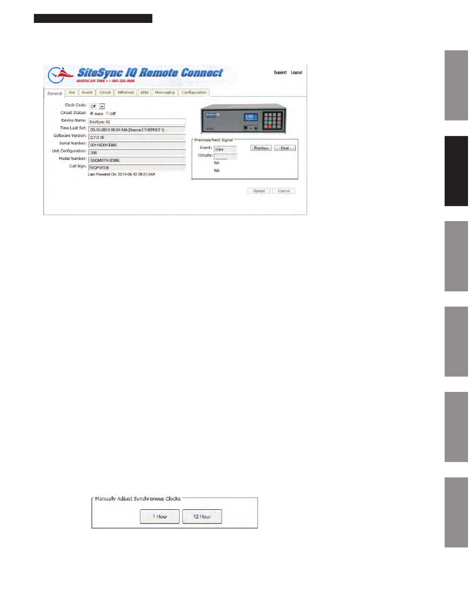
General Tab:
The General Tab contains information about the system controller as well as manual correction options for systems with clock relays.
Figure 4
1. Clock Code – This allows the user to select the clock code necessary to run their wired clocks. This field may not be selectable if
the system controller is not configured for clock relays.
2. Circuit Status – This will enable the bell relays if set to AUTO. This field may not be selectable if the system controller is not
configured for bell relays.
n
Note: Scheduled events will not run if this is not set to AUTO.
3. Device Name – This allows the user to name the system controller. This is useful for users that have more than one SiteSync IQ
system controllers to manage.
4. Time Last Set – This will display the last date and time the system controller was set. The source of which the date and time
was set will also be displayed.
n
Note: Ethernet 1 is the Primary Ethernet time server and Ethernet 2 is the Alternate time server as seen on Ethernet tab page 43.
5. Software Version – This will display the current software version of the SiteSync IQ system controller.
6. Serial Number – This is the serial number of the SiteSync IQ system controller.
7. Unit Configuration – This is the configuration code of the SiteSync IQ system controller.
8. Model Number – This is the model number of the SiteSync IQ system controller.
9. Call Sign – This is the call sign used by the SiteSync IQ system controller.
10.
Previous/Next Signal – This will display the next circuit activation to occur.
11.
Quiet Mode – This will display when the SiteSync IQ system controller enters Quiet Mode. Please reference Appendix J for
more information on Quiet Mode.
12.
Last Powered ON – This will display when the SiteSync IQ system controller was last turned on. This is useful to determine if
the unit has lost power.
13.
Battery Low – This indicates that the internal timekeeping battery need to be replaced. See Troubleshooting Section page 52
for more information.
Clock Codes:
Synchronous – If the system is to operate with synchronous clocks and the synchronous clock code is selected the Manually
Adjust Synchronous Clocks box will appear. For example, setting the Clock Code selector to 1 will enable synchronous clock
operation.
Figure 5
•
Pressing the 1 Hour button will advance the clocks by 1 hour. There will be approximately a 1-2 minute delay for each 1
Hour button press to allow the clocks to adjust.
•
Pressing the 12 Hour button will advance the clocks to the configured 12 hour mark. There will be a maximum delay of
13 minutes for each 12 Hour button press to allow the clocks to adjust.
Remote Connect Web Interface
Glossary
Appendix
Troubleshooting
Clock
Installation
System Contr
oller
Installation
Intr
oduction
Quiet Mode