Tachometer input connector, External vbus power connector, Tachometer input connector external v – Zilog ZUSBOPTS User Manual
Page 28: Figure 10. external power connector, External v, Power connector
UM026203-0115
MultiMotor Series Development Board
MultiMotor Series Development Kit
User Manual
21
Tachometer Input Connector
J5 is a two-terminal screw connector that allows easy connection of the AC induction
motor tachometer to the MultiMotor Series Development Board. The interface to the
MCU is a simple transistor circuit that squares off the incoming sine wave into 3.3 V digi-
tal pulses.
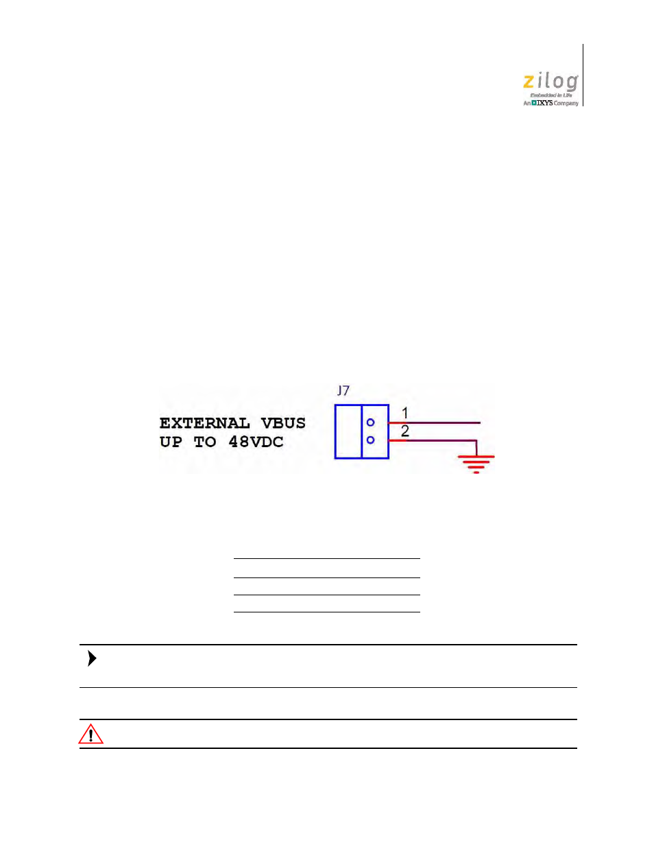
External V
BUS
Power Connector
J7 is a 2 terminal screw connector that allows easy connection of an external DC voltage
to the motor bus for larger or different motor types that require more power than the 24 V,
30W AC/DC adapter can provide. If the Linix motor provided with this kit is being used,
there is no need to use this connector, as all power is provided by the 24V DC, 30 W
adapter that comes with the kit and plugged into P1. Figure 10 shows the external power
connector.
Table 14 identifies the external V
BUS
power connector pins and their descriptions.
If using an external V
BUS
power supply, 24 V DC will still need to be provided to P1 or
J11 in order to power the gate drivers and electronics.
Bus Voltages higher than 48V DC may damage the Board and components.
Figure 10. External Power Connector
Table 14. External V
BUS
Power Connector
Signal
Pin
Description
V
BUS
1
24-48 Volts DC
GND
2
Ground
Note:
Caution: