I2c connector, 5 vin connector, C connector – Zilog ZUSBOPTS User Manual
Page 21: Connector
UM026203-0115
MCU Module
MultiMotor Series Development Kit
User Manual
14
I
2
C Connector
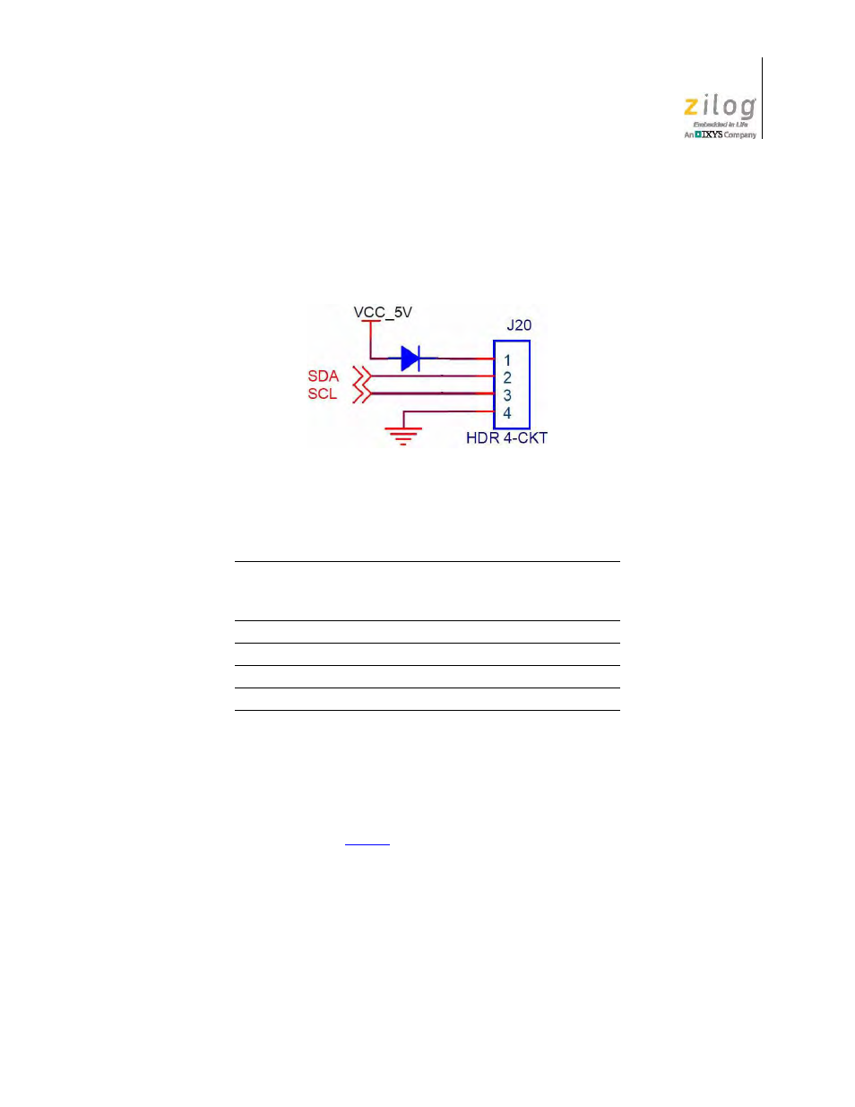
On some MCU modules, a 4-pin connector is provided to access the I
2
C functions of the
MCU. Figure 8 shows the I
2
C connector pin layout for the Z51F3220 MCU Module.
Table 6 identifies the I
2
C connector pin signals and their functions.
5 V
IN
Connector
For programming and debugging purposes, each MCU Module can be powered using a
bench power supply without being attached to the MultiMotor Series Development Board.
To power up the MCU Module in this manner, connect 5 V DC to the 5 V
IN
connector and
ground, as indicated in
Figure 8. I
2
C Connector, Z51F3220 MCU Module
Table 6. I
2
C Connector
Signal
Pin
Direction
(With Respect
To The MCU)
Description
V
CC
_5V
1
N/A
5V DC power.
SDA
2
I/O
Data.
SCL
3
I/O
Clock.
GND
4
N/A
Ground.