Debug connector, Figure 6, Debug connector, z16fmc mcu module – Zilog ZUSBOPTS User Manual
Page 19: Table 4, Debug connector signal descriptions
UM026203-0115
MCU Module
MultiMotor Series Development Kit
User Manual
12
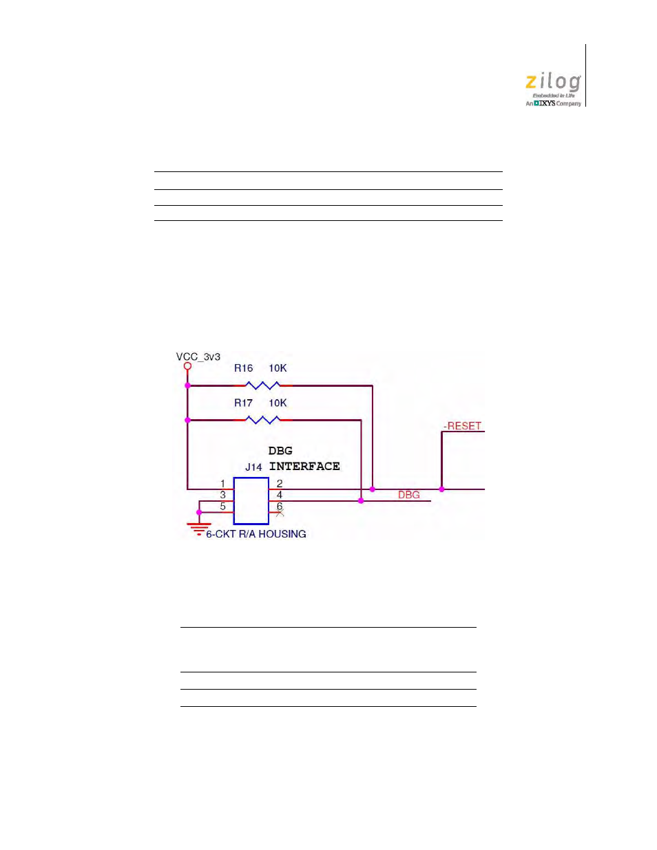
Debug Connector
A 6-pin debug connector is used in conjunction with the opto-isolated USB SmartCable
included with the MultiMotor Series Development Kit. This debug connector is used in
conjunction with ZDS II for programming and debug operations on the MCU Modules.
Figure 6 shows the debug connector’s pin layout for the Z16FMC MCU Module.
Table 4 identifies the debug connector signals and their functions.
15
PD6
NC
TEMP
16
GROUND
GROUND
GROUND
Figure 6. Debug Connector, Z16FMC MCU Module
Table 4. Debug Connector Signal Descriptions
Signal
Pin
Direction
(With Respect
To The MCU)
Description
V
CC
_3v3
1
N/A
3.3 V DC Power.
RESET
2
N/A
Active Low.
GND
3
N/A
Ground.
Table 3. Signal Header Pin Outputs (Continued)
Pin
Z16FMC (J13)
Z8FMC16100 (J10)
Z51F3220 (J8)