Uart connector, Figure 7, Uart connector, z16fmc mcu module – Zilog ZUSBOPTS User Manual
Page 20: Table 5
UM026203-0115
MCU Module
MultiMotor Series Development Kit
User Manual
13
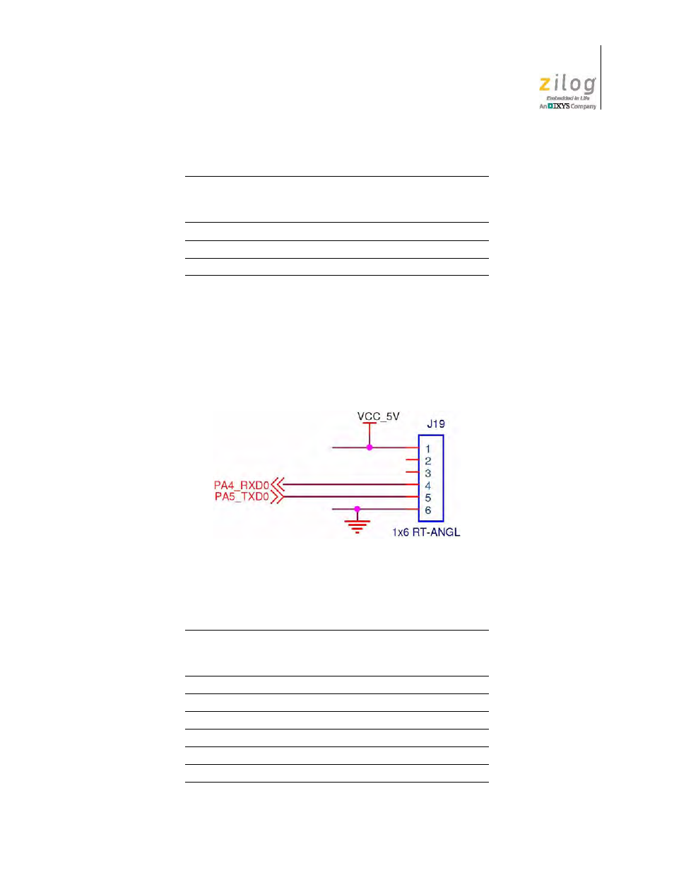
UART Connector
A 6-pin UART connector is used in conjunction with the opto-isolated UART-to-USB
adapter included with the MultiMotor Series Development Kit to allow the monitoring and
control of the motor from a PC. Figure 7 shows the UART connector pin layout for the
Z16FMC MCU Module.
Table 5 identifies the UART connector pin signals and their functions.
DBG
4
I/O
Debug.
GND
5
N/A
Ground.
NC
6
N/A
No Connect.
Figure 7. UART Connector, Z16FMC MCU Module
Table 5. UART Connector
Signal
Pin
Direction
(With Respect
To The MCU)
Description
V
CC
_5V
1
N/A
5 V DC power.
NC
2
N/A
No connect.
NC
3
N/A
No connect.
RXD
4
I
Receive.
TXD
5
O
Transmit.
GND
6
N/A
Ground.
Table 4. Debug Connector Signal Descriptions (Continued)
Signal
Pin
Direction
(With Respect
To The MCU)
Description