Zilog Z51F3221 User Manual
Page 25
UM025801-1112
Configure the Z8051 OCD and Z51F3221
Z51F3221 Development Kit
User Manual
18
4. Using the second USB-to-Mini-B cable, connect the standard USB end to the host
PC’s USB port.
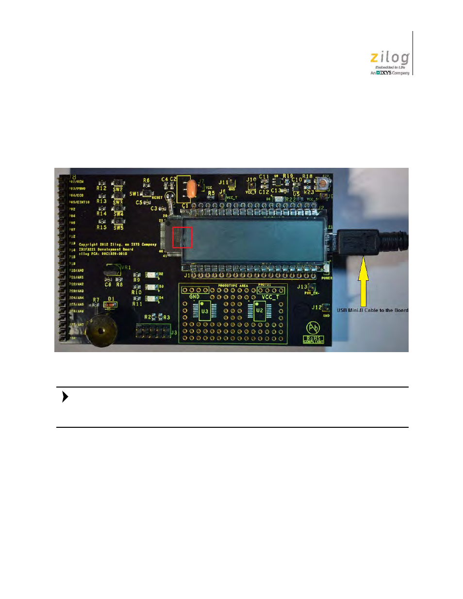
5. Connect the other end of this second Mini-B cable to the Z51F3221 Board’s P1 con-
nector to apply power to the Board. Note that the green LED D5 is ON; see Figure 14.
In the event that you later remove the LCD panel from the Board, observe its orientation in
Figure 14. The panel’s small plastic notch should be located in the position indicated by the
red square.
Figure 15 shows an example of a completed hardware and software setup.
Figure 14. Connecting the USB Mini-B Cable to the Board
Note: