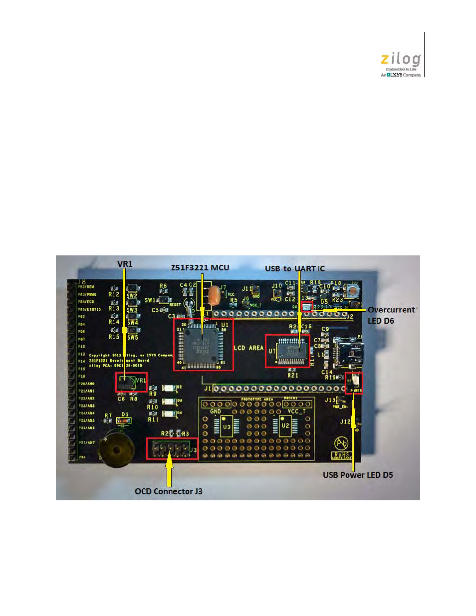
Figure 4, Z51f3221 development board: highlighted components – Zilog Z51F3221 User Manual
Page 12
UM025801-1112
Z51F3221 Development Board Description
Z51F3221 Development Kit
User Manual
5
•
USB-to-UART interface: U7
•
USB interface providing power and communication to the Board
•
Power supply level that can be adjusted with potentiometer R20
•
Overcurrent protection circuit on the Board: U6 and D6
•
External source of reference voltage (2.5 V) for the on-chip ADC: VR1
•
MCU current consumption measurement resistor R5 with test points J6 and J7
•
Buzzer: U4
•
8-digit, 14-segment LCD panel
•
Test points, headers and prototype area with two footprints
If a short on the Board should occur, or if its attached component(s) require more than
500 mA, the overcurrent protection functionality will trigger the red LED D6 to illuminate.
Figure 4. Z51F3221 Development Board: Highlighted Components