Zilog Z51F3221 User Manual
Page 24
UM025801-1112
Configure the Z8051 OCD and Z51F3221
Z51F3221 Development Kit
User Manual
17
Configure the Z8051 OCD and Z51F3221
Development Board
Observe the following procedure to set up and configure the Z8051 On-Chip Debugger
and the Z51F3221 Board.
Steps number 1 to 4 present the power-up sequence. Carefully follow these steps to avoid
encountering an improper connection or disconnection.
1. Connect the Z8051 On-Chip Debugger (OCD) to the host PC’s USB port.
2. Connect one end of the 10-circuit cable to the Z8051 OCD.
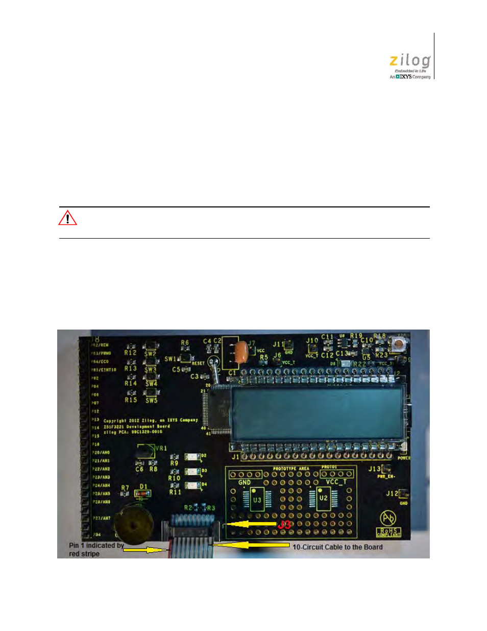
3. Connect the other end of the 10-circuit cable connector to the Z51F3221 Board’s J3
connector. Pin 1 of the cable connector is indicated by a red stripe, as shown in
Figure 13.
Figure 13. Connecting the 10-Circuit Cable to the Board
Caution: