Vectronics VEC-412K User Manual
Page 17
VEC-412K Owner's Manual
Rapid Battery Charger/Conditioner Kit
15
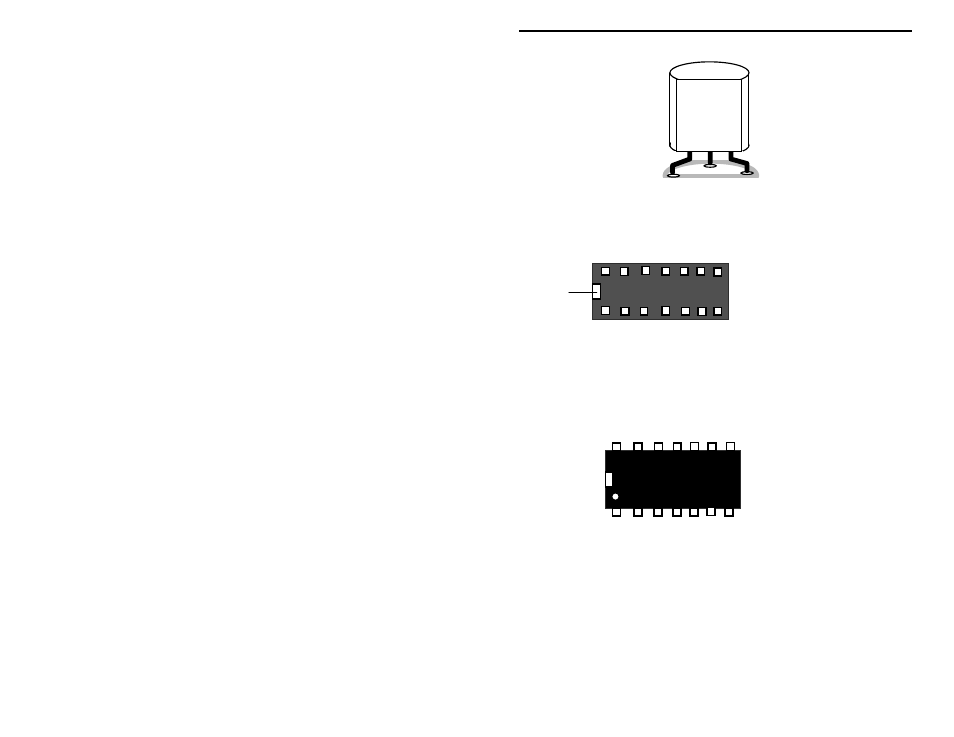
78L05
U2
Locate the 16-pin DIP IC socket. Notice that the socket is “keyed” to show
proper pin orientation.
1 2 3 4 5 6 7
14 13 12 11 10 9 8
Installation
Key
Pin Numbers
Top view of socket
! ! 9. Install and solder the 14-pin IC socket at location U1. Observe that
the key aligns with the legend outline on the pc board.
Locate the BQ2003 IC (14-pin DIP package).
1
Installation
Key
BENCHMARQ
BQ2003PN
The IC body has a small notch, or key, molded at one end, indicating pins 1 and
14. A small dimple-like body-molding is often found adjacent to pin 1. Some
IC packages may include both key indicators.
! ! 10. Align the key on the IC body so it corresponds with the key of socket
U1. Loosely insert the pins of the BQ2003 into socket U1. All 14
pins should fit freely into the socket openings. If not, straighten the IC
- SWR-66 (5 pages)
- SWR-584C (28 pages)
- AT-100 (5 pages)
- SWR-584B (25 pages)
- VEC-1856 (9 pages)
- VEC-1862 (9 pages)
- DL-2500 (2 pages)
- VEC-896 (17 pages)
- VEC-820K (20 pages)
- VEC-821K (22 pages)
- VEC-830K (18 pages)
- VEC-841K (27 pages)
- VEC-830KC (26 pages)
- VEC-821KC (5 pages)
- VEC-830KC (6 pages)
- VEC-884 (76 pages)
- VEC-1010K (31 pages)
- VEC-1340K (35 pages)
- VEC-1340K (27 pages)
- VEC-1340K (21 pages)
- VEC-1380K (39 pages)
- VEC-1012K (29 pages)
- VEC-1016K (23 pages)
- VEC-102K (37 pages)
- VEC-1180K (35 pages)
- VEC-131K (35 pages)
- VEC-121K (31 pages)
- VEC-1613 (4 pages)
- VEC-221K (35 pages)
- VEC-4001K (30 pages)
- VEC-1500K (68 pages)
- VEC-422K (27 pages)
- VEC-483K (17 pages)
- VEC-603 (2 pages)
- VEC-814 (4 pages)
- VEC-8218K (18 pages)
- VEC-841W (5 pages)
- VEC-862 (5 pages)
- CK-200 (8 pages)
- PMT-228 (20 pages)
- VEC-162 (10 pages)
- VEC-202 (8 pages)
- VEC-204 (8 pages)
- VEC-254 (4 pages)