Vectronics VEC-412K User Manual
Page 12
VEC-412K Owner's Manual
Rapid Battery Charger/Conditioner Kit
10
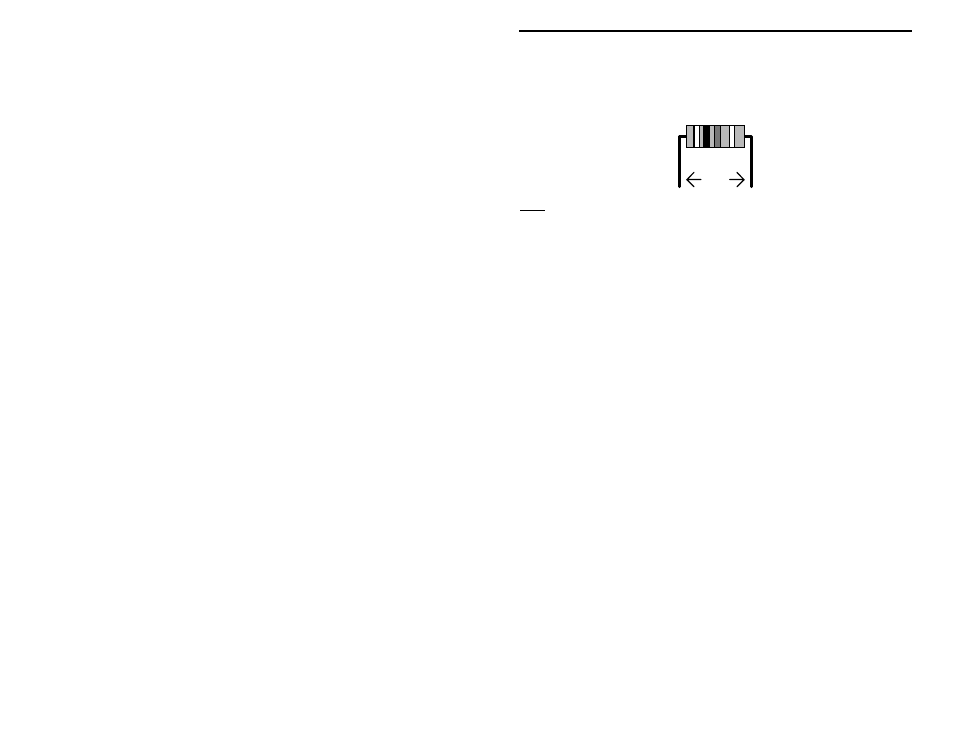
You will begin assembly by installing the ¼-watt fixed resistors. Because these
are all 5-percent tolerance ending with a fourth gold color band, you need only
read the first three bands of the color code during the following steps. All
resistor leads should be formed as shown below.
.4"
Note: The fourth resistor color band is for tolerance, and is not called out in the
following steps.
Begin by finding the six 1.5-ohm resistors (brown-green-gold-gold). Install and
solder at the following locations:
! ! 1. R16
1.5-ohm resistor (brown-green-gold)
! ! 2. R22
1.5-ohm resistor (brown-green-gold)
! ! 3. R23
1.5-ohm resistor (brown-green-gold)
! ! 4. R24
1.5-ohm resistor (brown-green-gold)
! ! 5. R25
1.5-ohm resistor (brown-green-gold)
! ! 6. R26
1.5-ohm resistor (brown-green-gold)
! ! 7. Locate the 220-ohm resistor (red-red-brown). Install and solder at
location R1.
Locate the three 1,000-ohm (1K-ohm) resistors (brown-black-red). Install and
solder at the following locations:
! ! 8. R3
1K-ohm (brown-black-red)
! ! 9. R12
1K-ohm (brown-black-red)
! ! 10. R17
1K-ohm (brown-black-red)
! ! 11. Locate the 27,000-ohm (27K-ohm) resistor (red-violet-orange). Install
and solder at location R5.
Locate the eleven 47,000 ohm (47K-ohm) resistors (yellow-violet-orange).
Install and solder at the following locations:
! ! 12. R2
47K-ohm (yellow-violet-orange)
! ! 13. R4
47K-ohm (yellow-violet-orange)
! ! 14. R6
47K-ohm (yellow-violet-orange)