Vectronics VEC-412K User Manual
Page 14
VEC-412K Owner's Manual
Rapid Battery Charger/Conditioner Kit
12
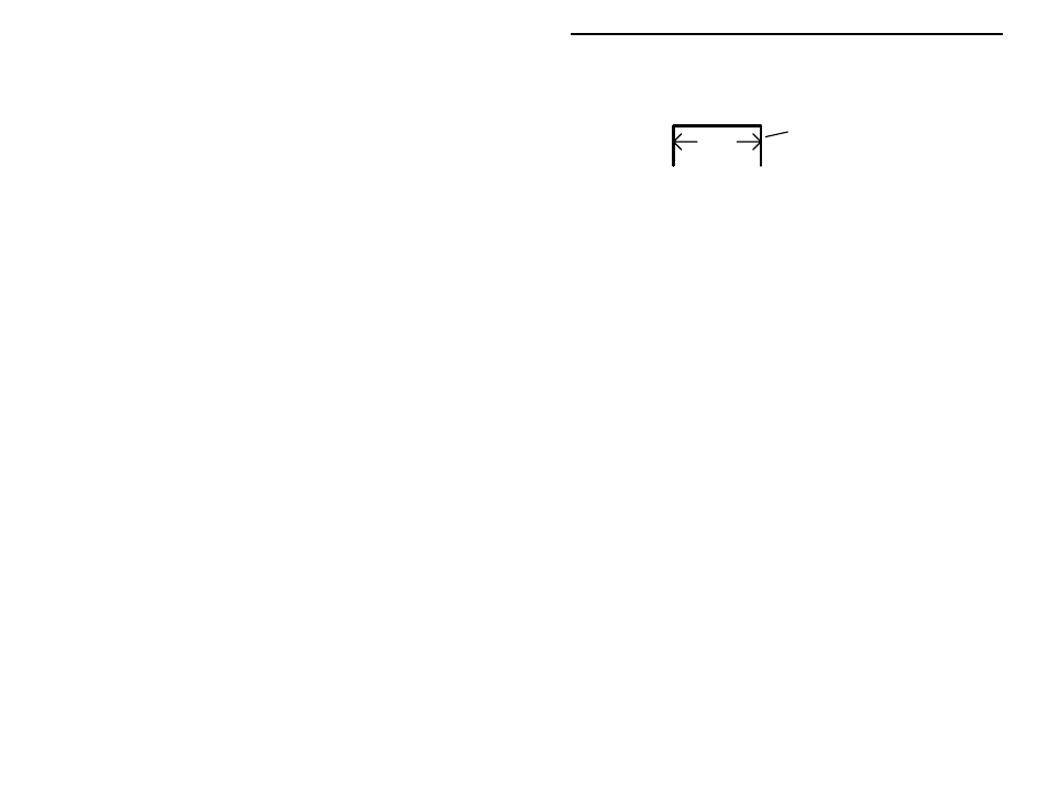
Use scrap resistor lead ends for use as jumper wires, as shown in the following
diagram. Use needle-nose pliers to form each one to fit properly at each
location, making sure each rests flat on the PC board when installed:
span
discarded lead end
Install and solder wire jumpers at the following locations:
! ! 1. JMP1 jumper wire
! ! 2. JMP2 jumper wire
! ! 3. JMP3 jumper wire
! ! 4. JMP4 jumper wire
! ! 5. JMP5 jumper wire
! ! 6. JMP6 jumper wire
! ! 7. JMP7 jumper wire
! ! 8. JMP8 jumper wire
! ! 9. JMP9 jumper wire
! ! 10. JMP10 jumper wire
Capacitor Installation:
Locate the five .1-uF ceramic disc capacitors (104 or .1). Install and solder at
the following locations:
! ! 1. C3
.1-uF ceramic disc capacitor (104 or .1)
! ! 2. C4
.1-uF ceramic disc capacitor (104 or .1)
! ! 3. C5
.1-uF ceramic disc capacitor (104 or .1)
! ! 4. C6
.1-uF ceramic disc capacitor (104 or .1)
! ! 5. C7
.1-uF ceramic disc capacitor (104 or .1)
Locate the two 100-uF electrolytic capacitors. Note that these are polarized
devices—they must be installed with regard to lead polarity! Carefully observe
the polarity markings on the board silk-screen, and the pictorial diagram before
soldering! Install and solder at the following locations:
! ! 6. C1
100-uF electrolytic capacitor. Observe polarity!
! ! 7. C2
100-uF electrolytic capacitor. Observe polarity!