Vectronics VEC-412K User Manual
Page 15
VEC-412K Owner's Manual
Rapid Battery Charger/Conditioner Kit
13
This completes installation of the capacitors. Recheck all work done so far and
correct any misplaced components or bad solder joints.
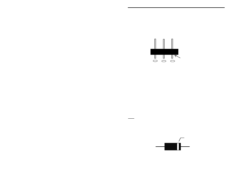
Header Installation:
Locate the six 3-position headers. Install and solder at the following locations:
Short pins into pc
board holes
! ! 1. HD1 Three-position header
! ! 2. HD2 Three-position header
! ! 3. HD3 Three-position header
! ! 4. HD4 Three-position header
! ! 5. HD5 Three-position header
! ! 6. HD6 Three-position header
Semiconductor Installation:
Note: All semiconductors are polarized devices. They must be installed as
directed. Use the pictorial drawing and the silk-screened legend on the pc
board to verify proper installation of these devices!
Locate the two 1N4001 silicon rectifier diodes. Install and solder at the
following locations—observe the orientation of the cathode lead:
Cathode
1N4001
! ! 1. D1
1N4001 diode, observe polarity!
! ! 2. D4
1N4001 diode, observe polarity!