Vectronics VEC-1016K User Manual
Page 7
[ ]
1
MC13135 IC (24 pin)
U1
[ ]
1
MC34119 IC (8 pin)
U2
Inductors/Filters/Crystals
[ ]
1
24" length, #22 coil wire
L1,L2
[ ]
1
.6 uH slug-tuned, shielded (yellow) L4
[ ]
1
660 uH adjustable, shielded (black) L5
[ ]
1
10.245 crystal
Y1
[ ]
1
10.7 MHz ceramic filter (SFE10.7J) FL1
[ ]
1
455 kHz ceramic filter (55D or 55F) FL2
Switches/Jacks/Misc
[ ]
1
DPDT push-button power switch
SW1
[ ]
1
RCA phono jack, pc-mounted
J1
[ ]
1
3.5mm stereo jack (mini-jack)
J2
[ ]
1
9-volt battery snap clip
[ ]
1
plastic cable tie
[ ]
1
PC board
[ ]
1
VEC-1016 Manual
(7 Parts Placement Diagram)
(8 Step-By-Step Construction)
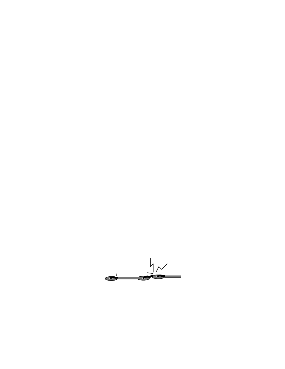
In these instructions, when you see the term install, this means to locate, identify, and
insert the part into its mounting holes on the PC board. This includes pre-bending or
straightening leads as needed so force is not required to seat the part. Once a component
is mounted, bend each lead over to hold it in place. Use sharp side-cutters to clip off
excess lead length before soldering. Make sure trimmed leads don't touch other pads and
tracks, or a short circuit may result:
Good
Not Good
The term solder means to solder the part's leads in place, and to inspect both (or all)
solder connections for flaws or solder bridges. Nip off excess protruding leads with a
sharp pair of side cutters. Generally, it's easier to install small close-to-the-board parts
first, and then mount larger stand-up parts second. Delicate parts, such as air-wound,
coils go on the PC board last.