Vectronics VEC-1016K User Manual
Page 17
Option 1: Calibrating with a Signal Generator or FM-Service Monitor
Set the generator up as follows:
Frequency:
50.0
MHz
Output Level:
10 uV (-90 dBm)
Modulation:
1-kHz tone at 5-kHz FM deviation
Connect the generator output to your VEC-1016K antenna jack using a 50-ohm patch
cable. Plug in headphones or external speaker to monitor generator signal.
[ ] Set TUNE to 50 MHz (fully clockwise) and SQUELCH counter-clockwise (open).
[ ] Power the radio and set VOLUME for a comfortable level.
[ ] Slowly tune L4 back and forth with an insulated tuning wand to locate the 50-MHz
test signal.
Important Note: The receiver's 10.245-MHz local oscillator's generates a 5th harmonic
on 51.225 MHz. If you tune across this signal, it will be heard as a strong unmodulated
carrier. Don't mistake this signal for your signal generator's output signal!
Option 2: Calibrating with a Antenna Analyzer
Any MFJ or Autek antenna analyzer with VHF coverage may be used to generate an
alignment signal. Set the analyzer to 50.0 MHz and position a few feet from the VEC-
1016. Do not connect the analyzer directly to your VEC-1016, or damage may result.
Install a 47-ohm resistor on the VEC-1016K antenna jack and follow the test procedure
outlined above for using a signal generator.
Option 3: Calibrating with a Frequency Counter
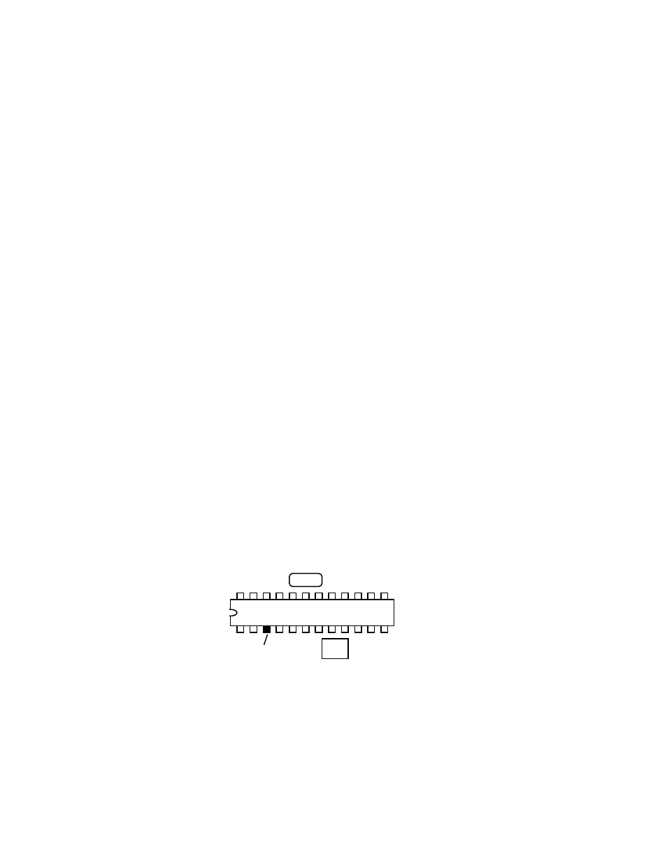
Your VEC-1016K features a buffered test point for measuring oscillator frequency with a
digital counter. Locate this point on the diagram below:
FL1
FL2
U1, MC13135
3
Test Point
Connect Counter Here
[ ] Connect the frequency-counter ground lead to a ground point (case or PC board).
[ ] Set the TUNE to 50 MHz (fully clockwise) and apply power.
[ ] Touch counter probe to pin-3 and adjust L4 for a counter reading of 39.3 MHz.