Vectronics VEC-1016K User Manual
Page 11
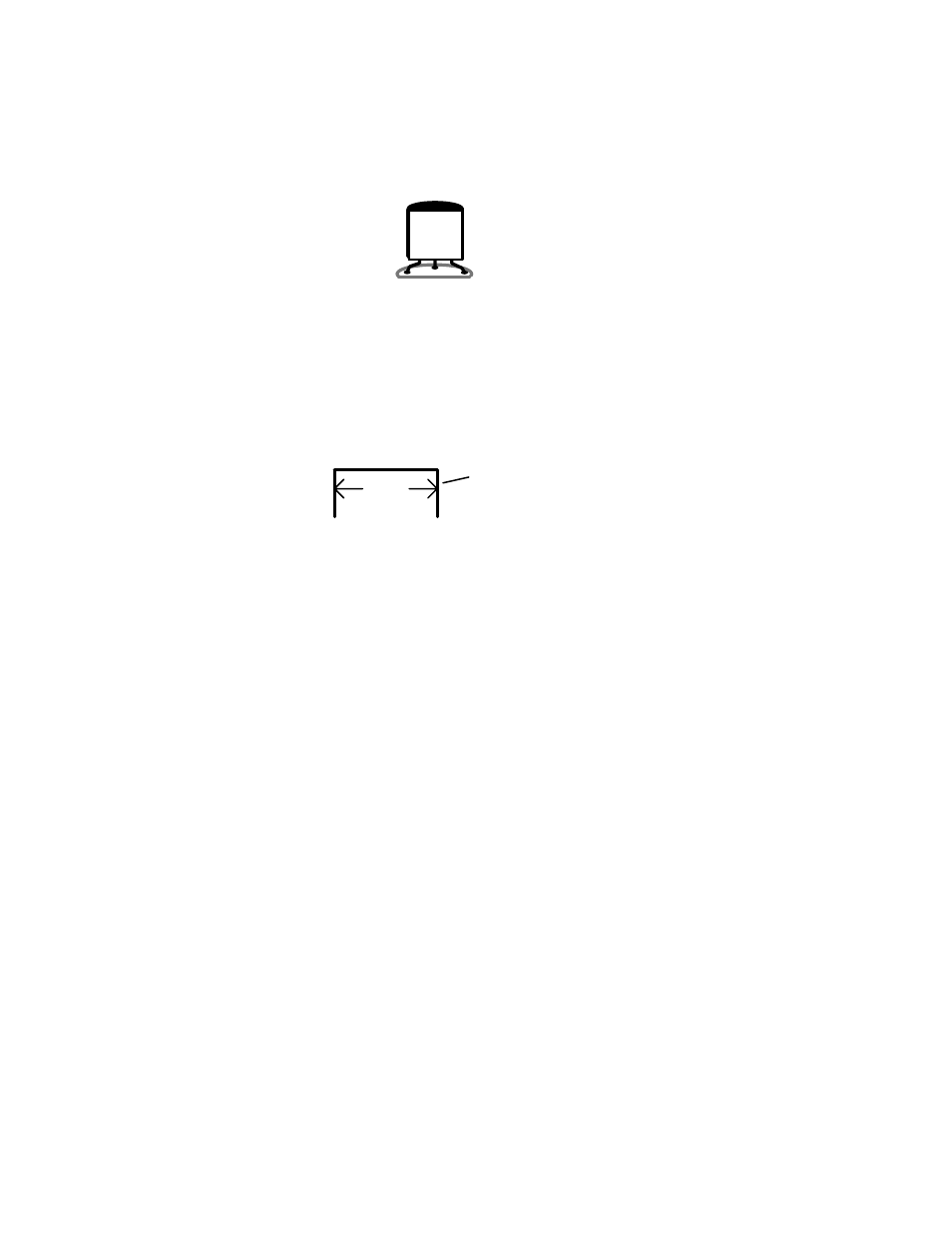
Locate the 2SC2498 plastic transistor and note its flat side. Position at Q1, as indicated
by the outline on the pc board. Gently pre-form the leads so the case is spaced
approximately .15" above the pc board surface when leads are fully inserted (see below).
2SC
2498
[ ] Install the 2SC2498 at Q1 and solder.
Your kit has six (6) jumper wires to install. Each should be pre-formed from a bare
length of discarded component lead, as shown below. The approximate distance between
mounting holes is given to help you pre-form each one. When installed, each jumper
should lay flat against the PC board.
span
discarded lead end
[ ] Make a jumper with a .2" span. Install at JMP1 and solder.
[ ] Make a jumper with a .25" span. Install at JMP2 and solder.
[ ] Make another jumper with a .25" span. Install at JMP3 and solder.
[ ] Make a jumper with a .3" span. Install at JMP4 and solder.
[ ] Make a second jumper with a .3" span. Install at JMP5 and solder.
[ ] Make a third jumper with a .3" span. Install at L3* and solder.
*Important Note: Inductor L3 is not used with the 49 MHz version of this kit. A jumper
is used in its place.
Locate the 10.7-MHz ceramic filter (looks like a square disc-ceramic capacitor with three
pins, marked 10.7J). This part is unpolarized and may be installed either way.
[ ] Install the 10.7-MHz filter at FL1 and solder.
Locate the 455-kHz ceramic filter (a small black cube with three pins marked 55D or
55F). This it will only fit one way on the PC board.
[ ] Install the 455-kHz filter at FL2 and solder.
[ ] Find the 3.5 mm stereo mini-headphone jack. Install and solder at J2.
[ ] Find the RCA phono jack. Install at J1 and solder all four taps.
[ ] Locate push-button power switch SW1. Install at SW1 and solder.