Vectronics VEC-1012K User Manual
Page 15
VEC-1012K Owner’s Manual
15
! ! Install the 9-volt battery snap clip. The red lead is installed at (+ 9V), and
the black at GND. Solder in place.
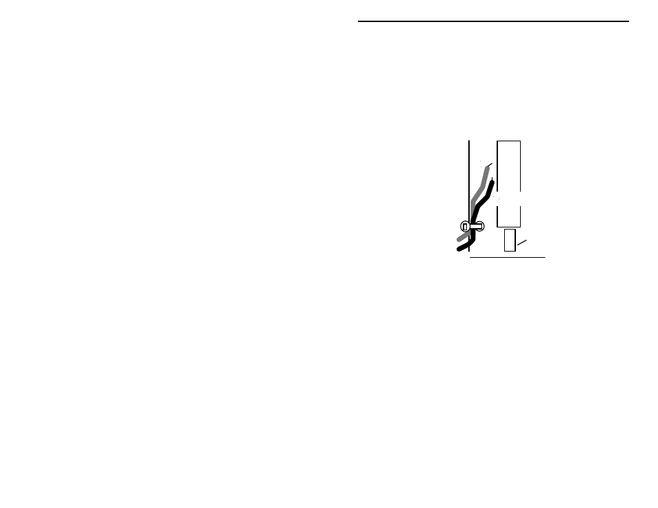
! ! Stress relief is provided to prevent battery leads from flexing and
eventually breaking at their connection point. Find a hole part-way back
on the left edge of the PC board (not to be confused with the board's
mounting holes at the front and back). Use the plastic tie-wrap provided
in your kit to secure the battery leads in place, as shown below. Insert the
tie-wrap through the hole, close it over the wires, and pull tight. Nip off
the excess end.
Tie-wrap
black
+
red
SW1
Push-rod
Finally, install receiver ICs U1 and U2. Before doing this, inspect both devices
carefully and straighten any bent or crooked pins. Use extreme care during
insertion, and move slowly. It's very easy to miss a pin opening and fold a IC
pin underneath the body of the device.
Locate U2, the MC34119 audio-amplifier IC (8 pins). Position its keyed (or
notched) end to correspond with the key marked on the pc board at U2.
Carefully align the pins with the U2 mounting holes before inserting.
! ! Install the MC34119 IC at U2, checking carefully that all 8 pins enter
their respective mounting holes. Solder each pin in place.
Locate the MC13135 Receiver IC (24 pins). Position the keyed end to
correspond with the key marked on the pc board at U1. Carefully align the pins
with the U1 mounting holes before inserting.
! ! Install the MC13135 IC at U1 and solder each pin in place.
! ! Inspect the pads under both ICs carefully for solder bridges and cold-
solder (use a magnifying glass, if available). Correcting any problem
before proceeding.