5 jumper settings – NEXCOM NEX 883 User Manual
Page 21
Copyright © 2011 NEXCOM International Co., Ltd. All Rights Reserved.
10
Chapter 2: Installation
NEX 883 User Manual
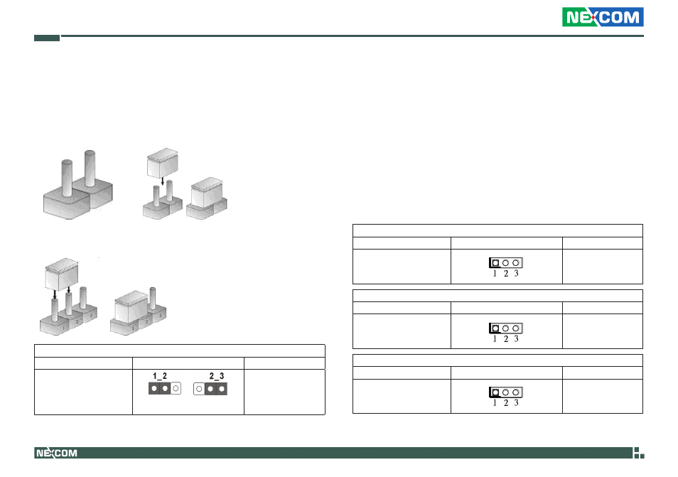
Clear CMOS Jumper
Jumper
Setting
Description
(3-pinCLRCMOS1)
(see p.8, No. 28)
Panel Power Selection
Jumper
Setting
Description
(3-pin PNL_PWR1)
(see p.8, No. 2)
1-2 : +3V
2-3 : +5V
Backlight Power Selection
Jumper
Setting
Description
(3-pin BKT_PWR1)
(see p.8, No. 3)
1-2 : +5V
2-3 : +12V
ATX/ AT Mode Selection
Jumper
Setting
Description
(3-pin PWR_JP1)
(see p.8, No. 41)
1-2 : AT Mode
2-3 : AXT Mode
2.5 Jumper Settings
The illustration shows how jumpers are setup. When the jumper cap is
placed on pins, the jumper is “Short”. If no jumper cap is placed on pins,
the jumper is“Open”. The illustration shows a 3-pin jumper whose pin1
and pin2 are“Short”when jumper cap is placed on these 2 pins.
Three-Pin Jumpers: Pins 1 and 2 Are Short
Note: CLRCMOS1 allows you to clear the data in CMOS. To clear and
reset the system parameters to default setup, please turn off
the computer and unplug the power cord from the power supply.
After waiting for 15 seconds, use a jumper cap to short pin2
and pin3 on CLRCMOS1 for 5 seconds. However, please do not
clear the CMOS right after you update the BIOS. If you need to
clear the CMOS when you just finish updating the BIOS, you
must boot up the system first, and then shut it down before you
do the clear-CMOS action. Please be noted that the password,
date, time, user default profile and MAC address will be cleared
only if the CMOS battery is removed.
Default
Clear CMOS