Chipset – NEXCOM NISE 3520 User Manual
Page 82
Copyright © 2013 NEXCOM International Co., Ltd. All Rights Reserved.
69
Chapter 4: BIOS Setup
NISE 3520 Series User Manual
Chipset
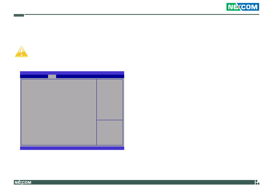
This section is used to configure the system based on the specific features
of the chipset.
Setting incorrect field values may cause the system to malfunc-
tion.
BIOS SETUP UTILITY
Version 2.00.1201. Copyright (C) 2009 American Megatrends, Inc.
CPU Type
Total Memory
Memory Slot 0
Memory Slot 1
CAS# Latency (tCL)
RAS# Active Time (tRAS)
Row Precharge Time (tRP)
RAS# to CAS# Delay (tRCD)
Write Recovery Time (tWR)
Row Refresh Cycle Time (tRFC)
Write to Read Delay (tWTR)
Active to Active Delay (tRRD)
Read CAS# Precharge (tRTP)
Initiate Graphic Adapter
VT-d
IGD Memory
Arrandale
1024 MB (DDR3 1066)
1024 MB (DDR3 1066)
0 MB (DDR3 1066)
7
20
7
7
8
60
4
4
5
[PEG/IGD]
[Disabled]
[32M]
Chipset
→ ←:
Select Screen
↑↓:
Select Item
Enter: Select
+/-: Change Opt.
F1: General Help
F2: Previous Values
F3: Optimized Defaults
F4: Save ESC: Exit
Initiate Graphic Adapter
Selects the graphics controller to use as the primary boot device.
VT-d
The options are Enabled and Disabled.
IGD Memory
Selects the internal graphics device’s shared memory size.
North Bridge