Locations of the jumpers and connectors, Nisb 3520 – NEXCOM NISE 3520 User Manual
Page 23
Copyright © 2013 NEXCOM International Co., Ltd. All Rights Reserved.
10
Chapter 2: Jumpers and Connectors
NISE 3520 Series User Manual
Locations of the Jumpers and Connectors
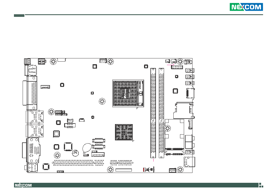
NISB 3520
The figure below is the top view of the NISB 3520 main board which is the main board used in the NISE 3520 Series system. It shows the locations of the
jumpers and connectors.
J20
J19
IDE1
CN20
CN19
CN18
J18
J6
SW1
DIMM1
DIMM2
J4
LED4
LED1
LED2
LED3
CN10
J2
J14
J1
CN5
BAT1
CN7
CN8
BZ1
J13
J15
CN9
CN11
CN6
CN3
J9
JP2
JP3
JP4
J8
JP1
CN1
CN2
J12
J5
CON1
HDMI
J3
This manual is related to the following products: