Reset button pin header, Pwr_led/hdd_led/smb_bus/s3/sw_on/reset – NEXCOM NISE 2400 User Manual
Page 45
Copyright © 2015 NEXCOM International Co., Ltd. All Rights Reserved.
31
NISE 2400 Series User Manual
Chapter 2: Jumpers and Connectors
1
2
Reset Button Pin Header
Connector type: 1x2 2-pin header, 2.0mm pitch
Connector location: JP12
Pin
definition
1
PMC_RSTBTN#
2
GND
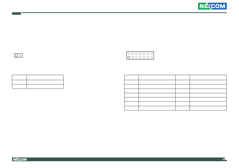
PWR_LEd/Hdd_LEd/SMB_BUS/S3/SW_ON/RESET
Connector type: 2x7 14-pin header, 2.0mm pitch
Connector location: JP3
1
7
2
14
Pin
definition
Pin
definition
1
PWR_LED_N
2
POWER_LED_PWR
3
HDD_LED_N
4
HDD_LED_PWR
5
SMB_CLK
6
SMB_DATA
7
3VSB
8
GND
9
SLP_S3#
10
PSON
11
PBT_SW
12
GND
13
PM_RESET#_J
14
GND
This manual is related to the following products: