Audio connectors, Led indicators, Audio connectors led indicators – NEXCOM NISE 2400 User Manual
Page 32
Copyright © 2015 NEXCOM International Co., Ltd. All Rights Reserved.
18
NISE 2400 Series User Manual
Chapter 2: Jumpers and Connectors
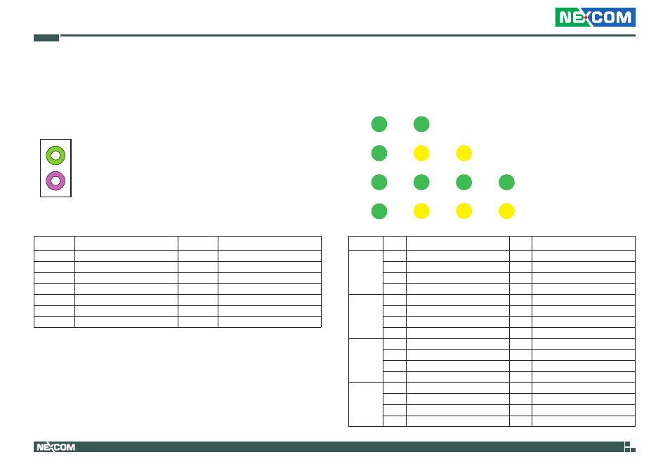
LEd Indicators
Connector location: LED2A, LED2B, LED2C and LED2D
Pin
definition
Pin
definition
LEd2A
A1
VCC5
C1
HDD_LED_N
A2
VCC3
C2
PWR_LED_N
A3
NC
C3
NC
A4
NC
C4
NC
LEd2B
A1
LAN2_ACT_CON
C1
LAN2_LED_ACT#
A2
LAN1_ACT_CON
C2
LAN1_LED_ACT#
A3
BAT_LED_N
C3
GND
A4
NC
C4
NC
LEd2C
A1
COM2_RXLEDP
C1
COM2_RXLEDN
A2
COM2_TXLEDP
C2
COM2_TXLEDN
A3
COM1_RXLEDP
C3
COM1_RXLEDN
A4
COM1_TXLEDP
C4
COM1_TXLEDN
LEd2d
A1
VCC5
C1
GPO_PR3
A2
VCC5
C2
GPO_PR2
A3
VCC5
C3
GPO_PR1
A4
VCC5
C4
GPO_PR0
LED2A
LED2B
LED2C
LED2D
GPO1
TX1
RX1
BATT
TX2
PWR
LAN1
RX2
HDD
CFast
LAN2
GPO2
GPO3
GPO4
Audio Connectors
Connector type: 2x 3.5mm TRS
Connector location: CN7A (Mic-in) and CN7B (Line-out)
Pin
definition
Pin
definition
1
R_CH_GND
2
MIC1_L3
3
MIC_GND
4
MIC_JD
5
MIC1_R3
MH1
R_CH_GND
MH2
R_CH_GND
MH3
R_CH_GND
MH4
R_CH_GND
NH1
NC
22
OUT_L
23
AGND
24
EXLINEOUT_JD
25
OUT_R
Line-out
Mic-in