Nisb 2400, Ac2 ac3 ac4, Chapter 2: jumpers and connectors – NEXCOM NISE 2400 User Manual
Page 25: Jp6 jp16, Jp15, Jp12 cn9 jfw1, Nise 2400 series user manual, Jp14, Jp13
Copyright © 2015 NEXCOM International Co., Ltd. All Rights Reserved.
11
NISE 2400 Series User Manual
Chapter 2: Jumpers and Connectors
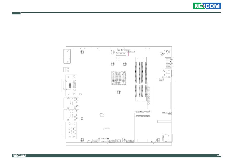
Locations of the Jumpers and Connectors for NISB 2400
NISB 2400
The figure below is the top view of the NISB 2400 main board which is the main board used in the NISE 2400 series. It shows the locations of the jumpers and
connectors.
J4
19
1
+
S1
PC1
S7
J2
2
1
52
18
16
2
51
17
15
1
CN3
1
3
CN8
JP11
JP8
CON1/J4
CN5
COM1
CN4
JP5
J3
CN1
DIMM2
1
2
72
74
71
73
204
203
DIMM1
1
2
72
74
71
73
204
203
9
18
17
10
8
5
4
CN5
1
Y
G/R
19
9
18
17
10
8
5
4
CN4
1
Y
G/R
19
25
22
5
2
CN7
CN2
H2
H1
H9
H11
H6
H8
J5
1
6
16
1
9
8
24
17
CON1
JP6
JP16
1
3
JP7
1
3
10
1
J3
+
JP1
1
4
4
1
JP10
CN7
LED2A
LED2B
LED2C
LED2D
1
2
9
10
JP2 JP4
JP3
JP1
CN2
CN6
8
1
2
7
4
1
1
2
13
14
3
1
3
1
JP15
JP14
3
JP13
1
3
2
JP11
2
1
JP12
CN9
JFW1
18
14
10
15
6
9
5
1
COM1
5
1
J9
5
1
J8
5
1
JP9
6
1
J1
1
2
19
20
CN1
U38
DA
1
AC1
DA
2
DA
3
DA
4
AC2
AC3
AC4
AA4
BC4
BA4
CC
4
CA
4
DC4
1
2
3
4
JP5
JP8
4
3
2
1
JFW1
56
1
2
USB3.0
CFast
SIM Card
Push Button
9-30V
DC Input
COM1/COM2
LAN2/USB2.0
LAN1/USB2.0
DVI-I/HDMI
Remote Power
On/Off
Mic-in
Line-out