2 cp1 and cp3 pin diagrams of in- and outputs, Cp1 and cp3 pin diagrams of in- and outputs, Mt + ht - mt - ht – KLING & FREITAG K&F ACCESS T9 User Manual
Page 32: Front rear, Red black blue white red black blue
User’s Manual
ACCESS SYSTEM
KLING & FREITAG GMBH ©1995-2009
Version 6.0, 17.03.2009
Page 32 of 60
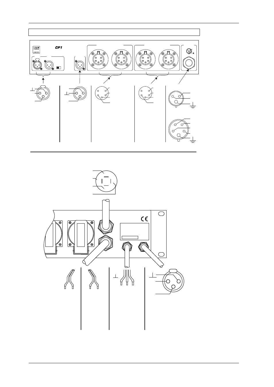
9.1.2
CP1 and CP3 Pin Diagrams of In- and Outputs
2
3
1
NEUTRIK
PUSH
1
3
2
NEUTRIK
1
3
2
NEUTRIK
1
2
3
4
5
1
2
3
4
5
1
2
3
4
5
1
2
3
4
5
BASS SPEAKER OUT
INPUT
LINK
BASS OUT
GROUND
ON OFF
TOP SPEAKER OUT
MAINS
ACCESS
L / +
N
-
Speaker B
L / +
L 1
N
L 2
L3
N
- Speaker A
+ Speaker A
+ Speaker B
+
-
-
+
CP 1
CP 3
MF
HF
1
3
2
-
+
4
5
3
2
1
4
5
3
2
1
2
3
1
-
+
+ MT
+ HT
- MT
- HT
1-
2-
1+
2+
IN
CONNECTOR
PANEL
CP3
Made in
Germany
Voltage:
Max. Total Output:
Protection Level
:
Serial Number
:
IP 40
115 / 230 VAC
3 x 16A
red
black
blue white
red
black
blue
-
+
2
3
1
-
+
Front
Rear
Outputs to
bass speaker
B5 / B10
Output to
high/mid
speaker
T5 / T9
Line level
input, e.g.
from mixing
console and
link connector
for linking the
LINE input
signal e.g. to
additional
amplifier racks
Power supply
Line level
output for
optional
linking of
signals proc-
essed by C5/9
Controller,
e.g. to addi-
tional amplifi-
ers
BASS A
To speaker
output of bass
amplifier / signal
for speaker A
BASS B
To speaker
output of bass
amplifier /
signal
for speaker B
IN
To input
of C5 -
Controller
MID-HIGH
To ‘‘SENSE-LOOP
HIGH + MID/LOW‘‘ ---
input connector of
C5 - Controller
TO BASS OUT
Controller signal
pick-off from the
input of the bass
amplifier (line level)