1 the access c5/9 controller, The access c5/9 controller, Connectors, controls and displays and of the c5/9 – KLING & FREITAG K&F ACCESS T9 User Manual
Page 23: Front view, Important
User’s Manual
ACCESS SYSTEM
KLING & FREITAG GMBH ©1995-2009
Version 6.0, 17.03.2009
Page 23 of 60
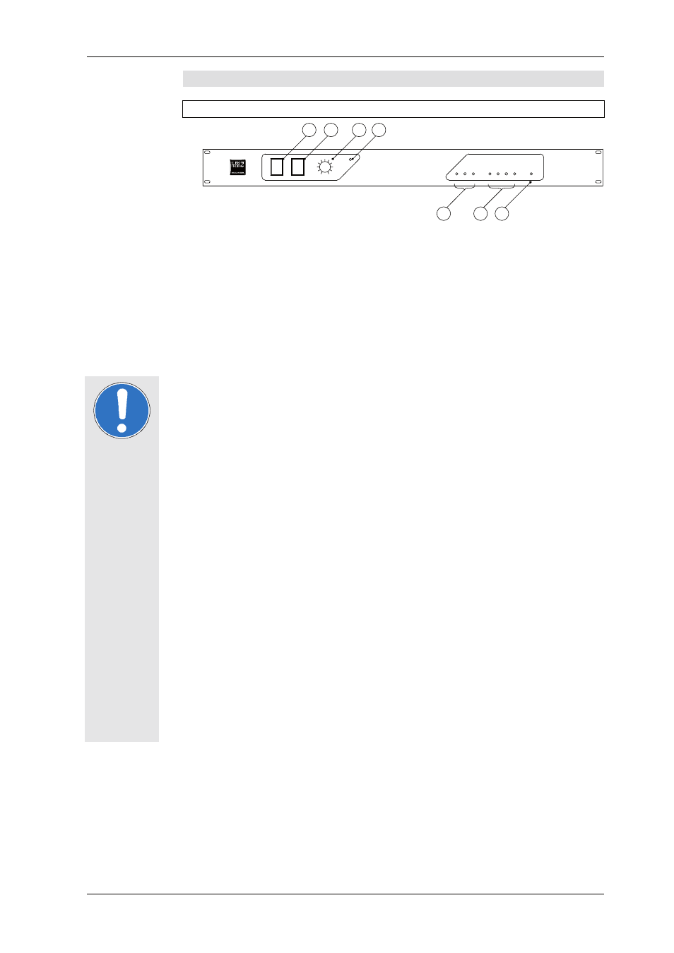
8.1
The ACCESS C5/9 Controller
8.1.1
Connectors, Controls and Displays and of the C5/9
1)
CLUSTER / SINGLE
When using the ACCESS System in a cluster (several speakers beside one an-other), better
coverage results may be obtained if the CLUSTER/SINGLE switch is turned to the CLUSTER
position. In this operational mode the increase in sound pressure levels in the low/mid ran-
ge area resulting from cluster operation is compensated, and a largely linear frequency re-
sponse is achieved.
2)
HIGHBOOST / NORMAL
The alignment of the ACCESS top speakers T5/T9 over long distances. High frequencies
are attenuated in the air over long distances. To compensate a decrease of high frequen-
cies, the HIGHBOOST should be switched on. The position NORMAL produces a linear fre-
quency response for short ranges.
3)
LEVEL
With the LEVEL control, the input level of the ACCESS Controller can be adjusted.
Normally this control should be set to 0dB in order to avoid an overload of the input circuit
or the outputs of the mixing console.
4)
CLIP
If this LED is lit up, the input of the C5/9 Controller is overloaded. Reduce the level on the
mixing console until the LED light remains off even at the highest volume.
5)
INPUT SIGNAL
The three SIGNAL LEDs indicate the signal level. If the red LED (+10dB) lights up often or
continuously, turn down the LEVEL control on the ACCESS C5/9 Controller and turn up
the power amplifiers.
6)
SENSE (GREEN) / LIMIT (RED)
The three SENSE/LIMIT-LEDs BASS, MID and HIGH have a double function.
a)
The LEDs light up green when the sense cable is connected and the C5/9 Controller is
receiving an output signal from the power amplifiers.
b)
When the relevant LED changes in colour from green to red, this indicates that the
C5/9 limiter is operating. A gradually setting-in RMS limiter and a fast peak limiter limit
the output power of the power amplifiers largely inaudibly down to the maximum
permissible value. If the red limiter LEDs light up frequently, then the level should be
slightly reduced. If necessary, the system should be supplemented with additional AC-
CESS speakers.
c)
The EXCURSION LED indicates that the excursion limiter has been started.This circuit
analyses the output and frequency of the mid-range amplifier and calculates the signal
for the limiter. The amplifier's signal is sent to the SENSE connector on the back side of
the C5/9, which limits theoutput signal to the maximum permissible value.
In exceptional cases, the Sense LEDs may still light up even when the power ampli-
fiers are turned off or disconnected. This situation is attributed to the ‘‘micro-
phone effect’’ of the speakers. If the cones are moved (i.e. from air movement of
other sound sources), the speakers produce voltage which may cause the LEDs to
light up.
7)
POWER ON
The POWER ON LED indicates that the system controller is on and operational. If the LED
does not light up after the equipment has been turned on, check the power supply or, if
necessary, replace the main fuse on the rear panel of the controller.
Front View
Important
1
2
3
4
7
6
5
CLUSTER
SINGLE
8
HIGH BOOST
NORMAL
A
C
C
ES
S C
5/
9
0
+6
LEVEL
CLIP
dB
SENSE (
GREEN
) / LIMIT (
RED
)
H
IG
H
+1
0
d
B
INPUT SIGNAL
-4
0
dB
0
d
B
M
ID
EX
C
U
RS
IO
N
BA
SS
O
N
POWER
A C C E S S
SYS TEM CONTROLLER