Tally out – Junger Audio d07 - Digital Transmission Processor User Manual
Page 12
A 2 –Installation
The digital audio level processor d07 can transmit specific device statuses via
parallel Tally lines.
use:
monitoring of the d07 status
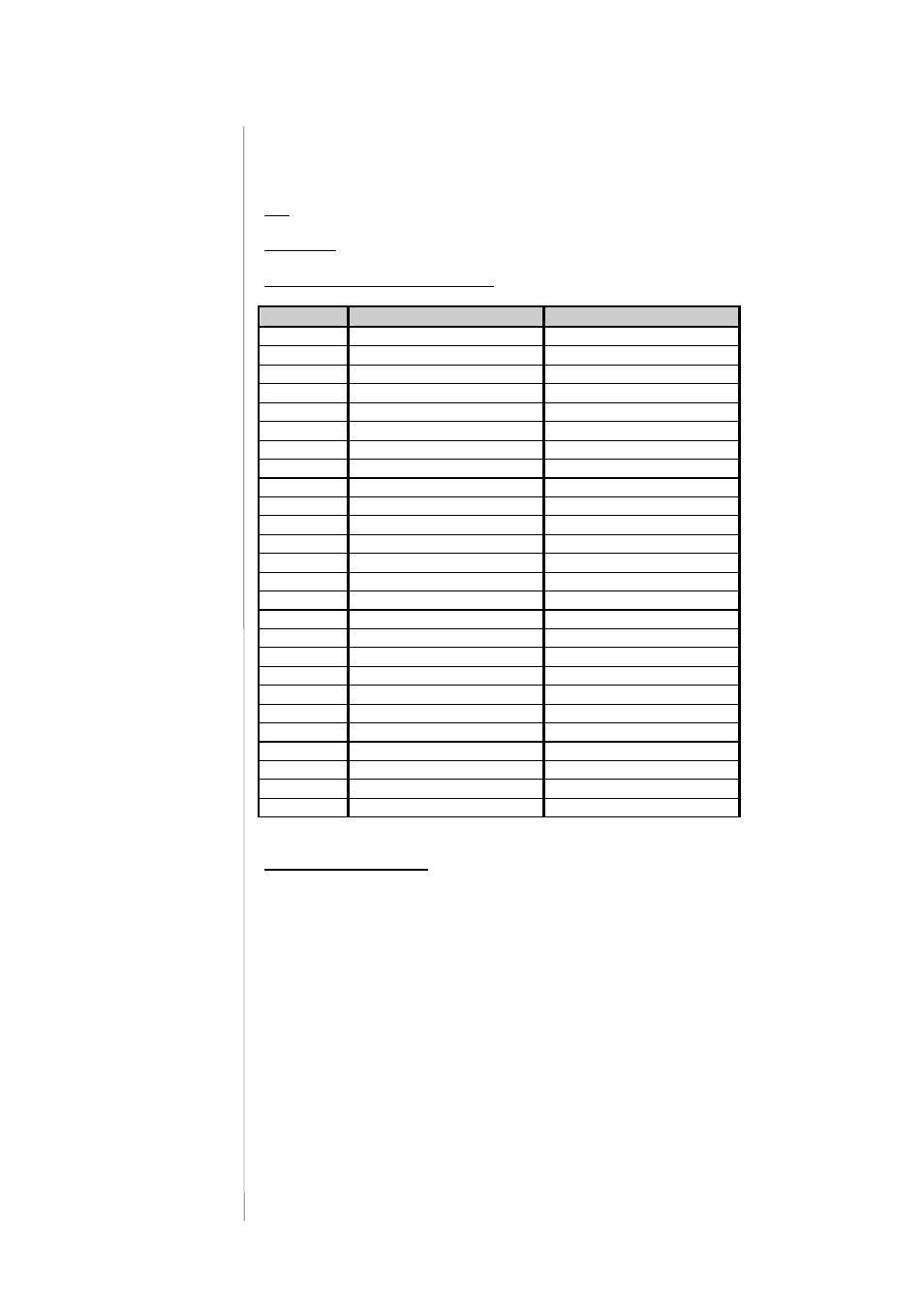
Connector :
D-SUB 25pin, female
Pin assignment of the connector :
Pin
Signal name
Functions
1
Tally 1 normally closed
2
Tally 1 normally opened
Defined by d07 config
3
TALLY 2 common
4
Tally 3 normally closed
5
Tally 3 normally opened
Defined by d07 config
6
TALLY 4 common
7
Tally 5 normally closed
8
Tally 5 normally opened
Defined by d07 config
9
Tally 6 common
10
Tally 7 normally closed
11
Tally 7 normally opened
Defined by d07 config
12
TALLY 8 common
13
+ 5V
110 Ohm
14
TALLY 1 common
15
Tally 2 normally closed
16
Tally 2 normally opened
Defined by d07 config
17
TALLY 3 common
18
Tally 4 normally closed
19
Tally 4 normally opened
Defined by d07 config
20
TALLY 5 common
21
Tally 6 normally closed
22
Tally 6 normally opened
Defined by d07 config
23
TALLY 7 common
24
Tally 8 normally closed
25
Tally 8 normally opened
Defined by d07 config
Shiled
Electrical specifications:
GPO (Tally)
potential free relay contact
common / normally closed / normally opened
24V - 1A
125V - 0,5A
P
max
= 62,5VA
Note : An internal auxiliary voltage feed is available on pin 9 via a 110Ohm
resistor. Ground is available from the shield of the connector only!
When using the auxiliary voltage feed, there is no electrical isolation given
anymore and the risk to inject unwanted noise is high!
2.8.2
TALLY OUT