Fixture internals, Leds and dies, Leds and clusters – ILUMINARC LΩGIC™ 16X36 User Manual
Page 9: Leds wiring, Maximum output line loading
LΩGIC™ 16X36 QRG
9
Fixture
Internals
To understand the maximum load allowed per output line, it is
important to know how the internal components are wired inside the
LΩGIC™ products.
LEDs and Dies
Single color LEDs have a single die (the part of the LED that generates
light). Tri-color LEDs have three dies (one for each color) on a single
package.
LEDs and
Clusters
Inside the
LΩGIC™ products, the LEDs are grouped in clusters of three
LED dies each.
· In a product with single color LEDs, three individual LEDs compose the
cluster.
· In a product with tri-color LEDs, a single tri-color LED makes up the
cluster.
LEDs Wiring
In an LED cluster, each LED die connects to an individual output
channel from the
LΩGIC™ controller. When a product has more than
one cluster, all the LED dies of a particular color connect to the same
output channel.
Maximum
Output Line
Loading
The
LΩGIC™ 16X36 controller has 16 output lines. You can select
each output line individually or you can select all output lines (Zone
Selection).
Each output line has three channels: Red, Green, and Blue.
Each of the three output channels can support up to 12 LED dies.
Therefore, the maximum number of LED dies supported per output line
is 36.
When connecting
LΩGIC™ products to the LΩGIC™ 16X36 controller, do
not exceed the maximum of 12 LED dies per output channel (36 LEDs
dies per output line).
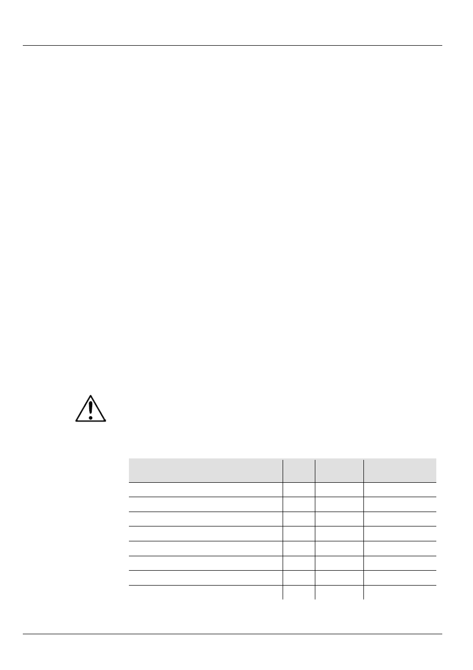
The table below shows the maximum number of
LΩGIC™ products
that can be loaded onto an output line per product model.
Model Name
Total
LEDs
Total LED
Dies
Max. Fixtures
per Output
Ilumiline
LΩGIC™ 24 RGB
24
24
1
Ilumiline
LΩGIC™ 24 Optic RGB
24
24
1
Ilumiline
LΩGIC™ 12 Optic RGB
12
12
3
Ilumipod
LΩGIC™ 12 Optic RGB
12
12
3
Ilumipod
LΩGIC™ 6 Optic RGB
6
6
6
Ilumipod
LΩGIC™ 3 Optic RGB
3
3
12
Ilumipod
LΩGIC™ Tri-1 RGB
1
3
12
Ilumipod
LΩGIC™ Tri-4 RGB
4
12
3