Installation, 1 physical layout – DekTec DTE-3114 IP to 4x QAM User Manual
Page 8
DTE-3114 – Networked Quad QAM Modulator
USER MANUAL
8
2. Installation
2.1 Physical layout
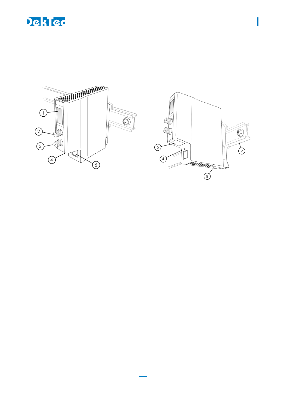
1.
LCD display
The LCD display indicates the device identifier and device status
information.
2.
Main RF output
F female connector, 75 Ohm impedance.
3.
Monitor RF output
F female connector, 75 Ohm impedance.
4.
Reset button
Button that can be operated with a paper clip. The function is to
reboot the DTE-3114, or enter failsafe mode if held pressed for
more than three seconds.
5.
RJ-45 Gigabit port
The Ethernet port is used to supply TS-over-IP input, Web and
SNMP management and (optionally) power supply from a
Power-over-Ethernet enabled network.
6.
Label
Label containing the device’s serial number and MAC address.
7.
Rail-mount system
The Rail-mount system is used to install the DTE-3114 on the
DekTec 19”-rack-mountable rail or a DIN Rail.
8.
24V DC power jack
An auxiliary power supply (24V/400mA) can be used when
Power-over-Ethernet is not available.