CRU DataPort 5 IDE/ATA-6 User Manual
Page 6
6. For DataPort V plus carriers, attach the Temperature Control Cooling Sen-
sor (TCCS) to the top of the hard drive with adhesive tape.
7. After the drive has been installed, replace the top and bottom covers.
8. Insert the carrier into the frame assembly. Ensure that the lock of the
DataPort is in the OPEN/OFF (vertical) position. Position the carrier on the
guide rails and then slide the carrier into the frame. Using thumb pressure,
fully seat the carrier in the frame and then lock the unit with the lock key
provided.
Installing a SATA Hard Drive in the Carrier
1. Remove the covers of the DataPort V or V plus carrier
Use the provided cover removal tool to lift off the cover or slide the covers
off the back of the DataPort carrier.
2. Install the SATA hard drive in your carrier.
Carefully connect the hard drive to the carrier board. Align the hard drive
with the side mount screw holes then use the provided screws to secure
the hard drive in position. For the DataPort V plus use a piece of adhesive
tape to attach the TCCS sensor (wire for regulating temperature control) to
the middle of the hard drive. Place the covers back on the DataPort V or V
plus carrier.
3. Insert the carrier in the frame assembly.
Slide the carrier into the frame and lock the carrier. The lock on the
DataPort V or V plus serves as the power ‘ON/OFF” switch. After the lock
is engaged the green LED will illuminate when the computer is powered
on.
You have finished the installation and your DataPort is ready to operate.
Operation
Note: The lock on the DataPort locks the carrier in place and also
serves as an ON/OFF switch for the power.
1. Turn the lock 90 degrees clockwise to the ON position before turning on
the computer.
Page 7
Page 8
Mounting an IDE Hard Drive in the Carrier
1. Using the cover removal tool supplied in your DataPort package or a flat-
head screwdriver, gently pry the top and bottom covers from the carrier
and set them aside.
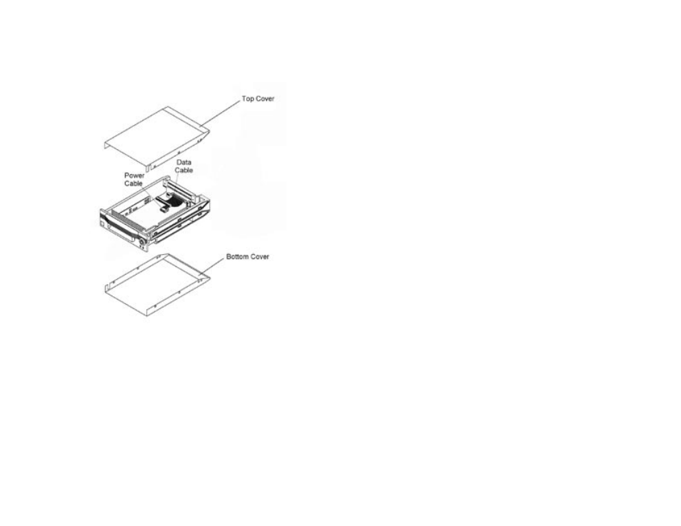
Diagram 7 – Inside view of an IDE carrier
2. For IDE hard drives, set the Master/Slave jumper on the drive before
placing the drive in the carrier.
3. Connect the DC power cable to the drive. Plug the 4-pin DC power cable
into the power connector on the drive and ensure it is fully seated.
4. Connect the data cable in the carrier to the drive.
5. Install the drive in the carrier. Place the drive in the carrier and use the
four screws provided to mount the drive. Position the cables inside the
carrier assembly so that they are completely enclosed within the carrier.