CRU DataPort 5 IDE/ATA-6 User Manual
Page 5
9. Connect the DC power cable to the frame by locating an available
4-pin DC power cable from the computer power supply and then
plugging it into the power plug on the frame.
Note: Currently, the Serial ATA DataPort can only be powered by the
standard AT 4-pin connector.
The frame installation is now complete.
Hard Drive Activity LED
The front of all DataPorts have two LEDs: a green LED that lights up
when the power to the hard drive is on, and a red LED that lights up
when activity is taking place on the hard drive (see Diagram 5).
Diagram 5 – Front view of DataPort
For SATA hard drives the DataPort V”plus” will show drive activity with
the red LED. For SATA drives on the DataPort V, the red LED will not
show drive activity.
Page 5
Page 6
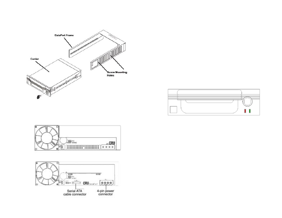
7. Using the screws provided, secure the frame assembly to the computer case
using the frame’s side mounting holes (see Diagram 2). Your DataPort also
has bottom mount holes in case you need to bottom mount the frame.
Diagram 2 – Carrier (with covers in place) and frame
8. Locate the data cable and connect it to the connector on the rear of the frame
(see Diagrams 3 and 4).
Diagram 3 – Rear view of Parallel IDE DataPort
Diagram 4 – Rear view of Serial ATA DataPort