Conta-electronics – CONTA-CLIP CMS-BS 100 User Manual
Page 3
CONTA-ELECTRONICS
CMS
CMS
CMS
CMS----BS100
BS100
BS100
BS100
Multi
Multi
Multi
Multi----function Multi
function Multi
function Multi
function Multi----channel converter
channel converter
channel converter
channel converter
Further information: www.conta-clip.com
Cat. No.: 95120.1
Further information: www.conta-clip.com
Function: inverter
Function: inverter
Function: inverter
Function: inverter
Select the input range:
DIP5 input1
DIP5 input1
DIP5 input1
DIP5 input1
DIP6
DIP6
DIP6
DIP6 input2
input2
input2
input2
value
value
value
value
off
off
0..10V / 0..20mA
on
on
0..5V / 0..10mA
Select the switching behaviour:
DIP7 output1
DIP7 output1
DIP7 output1
DIP7 output1
DIP8 output2
DIP8 output2
DIP8 output2
DIP8 output2
value
value
value
value
off
off
A
on
on
B
Function: RTD
Function: RTD
Function: RTD
Function: RTD
The value from input1 and/or input2 is forwarded inverted to resp. output1 and/or output2.
This function is selected by setting the dipswitches as shown below.
DIP1
DIP1
DIP1
DIP1
DIP2
DIP2
DIP2
DIP2
DIP3
DIP3
DIP3
DIP3
DIP4
DIP4
DIP4
DIP4
off
off
off
on
Select the input range:
input1
input1
input1
input1
input2
input2
input2
input2
DIP5
DIP5
DIP5
DIP5
DIP6
DIP6
DIP6
DIP6
DIP7
DIP7
DIP7
DIP7
DIP8
DIP8
DIP8
DIP8
value
value
value
value
off
off
off
off
0..10V / 0..20mA
off
on
off
on
0..5V / 0..10mA
on
off
on
off
2..10V / 4..20mA
on
on
on
on
1..5V / 2..10mA
Function: optocoupler out
Function: optocoupler out
Function: optocoupler out
Function: optocoupler out
The RTD function forwards a temperature range from -20..140ºC to the selected output
range, input1 to output1 and input2 to output2. This function is selected by setting the
dipswitches as shown below.
DIP1
DIP1
DIP1
DIP1
DIP2
DIP2
DIP2
DIP2
DIP3
DIP3
DIP3
DIP3
DIP4
DIP4
DIP4
DIP4
off
off
on
on
Select the input RTD:
DIP5 input1
DIP5 input1
DIP5 input1
DIP5 input1
DIP6 input2
DIP6 input2
DIP6 input2
DIP6 input2
RTD
RTD
RTD
RTD
off
off
NI1000
on
on
PT1000
Select the output range:
DIP7 output1
DIP7 output1
DIP7 output1
DIP7 output1
DIP8 output2
DIP8 output2
DIP8 output2
DIP8 output2
value
value
value
value
off
off
0..10V / 0..20mA
on
on
2..10V / 4..20mA
Function: digital in to digital out
Function: digital in to digital out
Function: digital in to digital out
Function: digital in to digital out
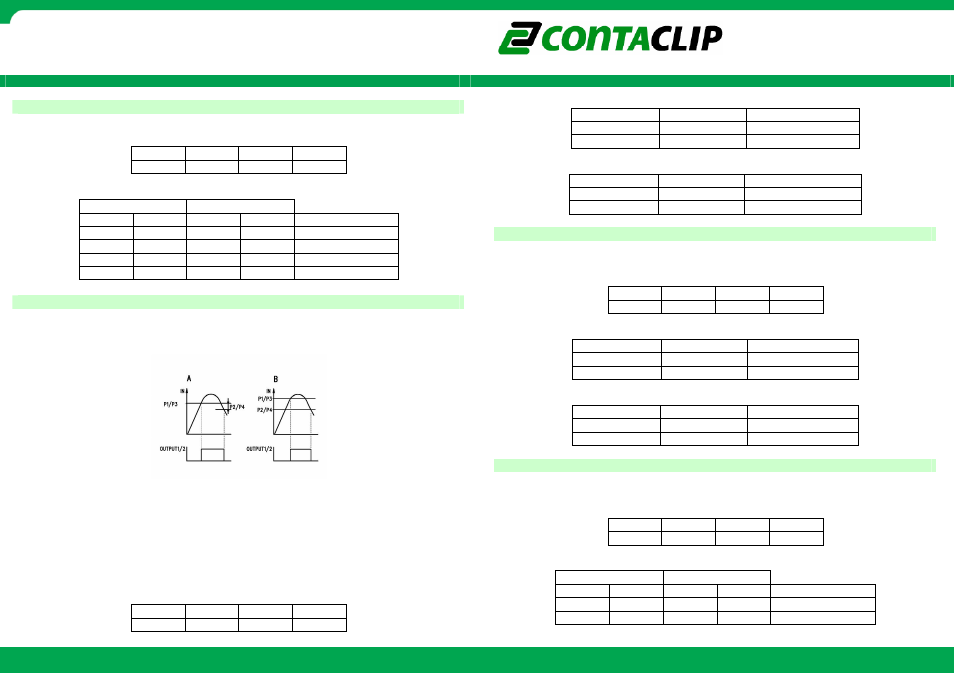
The optocoupler out function behaves as shown in the switching diagram. Potentiometer P1
an P2 represent the threshold for input1, potentiometer P3 and P4 represent the threshold for
input2. Input1 switches output1 and input2 switches output2.
A:
A:
A:
A: output1/2 switches on when value P1/P3 is reached. The output1/2 switches off
when value P1 - P2 / P3 – P4 is reached.
B:
B:
B:
B: output1/2 switches on when value P1/P3 is reached. The relays switches off when
value P2/P4 is reached.
All potentiometers represent a percentage from the selected input value. Full left turn is 0%
and full right turn is 100%.
This function is selected by setting the dipswitches as shown below.
DIP1
DIP1
DIP1
DIP1
DIP2
DIP2
DIP2
DIP2
DIP3
DIP3
DIP3
DIP3
DIP4
DIP4
DIP4
DIP4
off
off
on
off
Digital input1 and input2 will be forwarded to resp. output1 and output2.
This function is selected by setting the dipswitches as shown below.
DIP1
DIP1
DIP1
DIP1
DIP2
DIP2
DIP2
DIP2
DIP3
DIP3
DIP3
DIP3
DIP4
DIP4
DIP4
DIP4
on
off
off
off
Select the output type:
output
output
output
output1
1
1
1
output2
output2
output2
output2
DIP5
DIP5
DIP5
DIP5
DIP6
DIP6
DIP6
DIP6
DIP7
DIP7
DIP7
DIP7
DIP8
DIP8
DIP8
DIP8
value
value
value
value
off
off
off
off
not inverted
off
on
off
on
inverted