Conta-electronics – CONTA-CLIP CMS-BS 100 User Manual
Page 2
CONTA-ELECTRONICS
CMS
CMS
CMS
CMS----BS100
BS100
BS100
BS100
Multi
Multi
Multi
Multi----function Multi
function Multi
function Multi
function Multi----channel converter
channel converter
channel converter
channel converter
Further information: www.conta-clip.com
Cat. No.: 95120.1
Further information: www.conta-clip.com
Configuration
Configuration
Configuration
Configuration
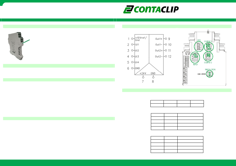
Connection diagram
Connection diagram
Connection diagram
Connection diagram
Configuration example
Configuration example
Configuration example
Configuration example
To open the module press the locking levers under the terminals with
a screwdriver.
The module is configured by setting the dip-switches and jumpers
according to this manual.
Connecting the module
Connecting the module
Connecting the module
Connecting the module
The pin configuration for I/O and power connection is shown on the top of the module.
The green Led on top indicates Power ON.
Input configuration
Input configuration
Input configuration
Input configuration
Function
Function
Function
Function: splitter
: splitter
: splitter
: splitter
The CMS-BS100 has 4 multifunctional inputs which can be configured for measuring voltage,
current, RTD and to detect digital signals. To configure the inputs a series of jumpers and/or
additional resistors(not included) have to be set according to the text on the PCB.
The inputs must be set as follows:
•
Uin: jumper on U, resolution: jumper on 2.5V, no resistor placed
•
Iin: jumper on I, resolution: jumper on 2.5V, no resistor placed
•
RTD: no jumper on input, resolution: jumper on 1V, resistor 18K2 0.1% placed
•
Digital in: jumper on U, resolution: jumper on 2.5V, no resistor placed
In the example drawing input1 is set to measure Voltage and input2 to measure current.
Output configuration
Output configuration
Output configuration
Output configuration
The CMS-BS100 has 2 multifunctional outputs which can be configured to output voltage,
current and digital signals. To configure the outputs a series of jumpers have to be set
according to the text on the PCB.
The outputs must be set as follows:
•
Uout: jumper on U, 2 jumpers on ANA
•
Iout: jumper on I, 2 jumpers on ANA
•
Digital out: no jumper on U/I, 2 jumpers on DIG
In the configuration example output1 is set to output current and output2 to output digital
signals.
Input1 is forwarded to both output1 and output2. This function is selected by setting the
dipswitches as shown below.
DIP1
DIP1
DIP1
DIP1
DIP2
DIP2
DIP2
DIP2
DIP3
DIP3
DIP3
DIP3
DIP4
DIP4
DIP4
DIP4
off
off
off
off
Select the input range:
DIP5
DIP5
DIP5
DIP5
DIP6
DIP6
DIP6
DIP6
value
value
value
value
off
off
0..10V / 0..20mA
off
on
0..5V / 0..10mA
on
off
2..10V / 4..20mA
on
on
1..5V / 2..10mA
Select the output range:
DIP7
DIP7
DIP7
DIP7
DIP8
DIP8
DIP8
DIP8
value
value
value
value
off
off
0..10V / 0..20mA
off
on
0..5V / 0..10mA
on
off
2..10V / 4..20mA
on
on
1..5V / 2..10mA