1 before start-up, 2 start-up, Efore start – CIRCUTOR FRE Series User Manual
Page 13: Tart, Ee fig. 5-4)
FRE / FRES
13 / 20
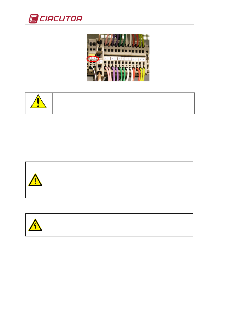
Fig. 5-4 .- Jumper for short-circuiting the secondary winding of the current transformer (CT).
Any time you wish to change or disconnect a current transformer from the filter
cabinet. it is important to install a jumper connecting S1 and S2.
6
START-UP OF A STATIC CAPACITOR BANK WITH DETUNED FILTER (FRE or FRES)
6.1 Before start-up
FRE and FRES filters have a built-in power factor regulator. Prior to start-up, the operation of such
regulator device must be known. For this reason, all capacitor banks and filters
come with the specific
instructions manual of the PF regulator used. Ensure you have this manual available before the
start-up process. In case of static banks the PF regulator must be MOS static output type (computer
Max f, computer Smart f , computer PlusTF or equivalent)
The set-up of the PF regulator controlling the filter and its optimum adjustment
during start-up requires the installation to have at least a 30 to 40% of rated load. If
the load during the start-up process is low , only a few steps will connect. In such
case, manually force the connection of all the steps in order to check them all.
During low load periods, manually connecting the full power of the filter bank is not
recommended, as in some cases resonance with the installation power
transformer could occur.
6.2 Start-up
SAFETY
Apply the safety regulations listed in section 2 of this manual before operating the
equipment.
The standards and applicable national laws of the country where the static filter
bank is installed or operated should be strictly followed.
•
Ensure that the inner circuit breaker that starts the regulator, shown as the control circuit protection in
Fig. 4-3 is connected
•
Connect the
FRE or FRES equipment to power supply and check that the PF regulator display
illuminates immediately. If not, stop and check the previous step.
•
Check the cosϕ indication of PF regulator display. If the indication is out of range 0.5 to 1, the current
transformer and / or the power supply to the regulator may be improperly connected. Most of the
regulators use only one current transformer. In this case, connect as per Fig. 6-2 (place the current
transformer in phase L1 and take the power voltage from phases L2 and L3)