CIRCUTOR CVM-BD Series User Manual
Page 21
-- Supply network analyzers CVM-BD-420-4 & CVM-BD-420-8 -- M98132301-20 --- Page Nº 20
- If you select “SET PAGE YES” , you can program the desired parameters in this
page :
xx A1
xx A2
xx A3
Parameter code ( set-up ) / Parameter symbol
SET-UP :
- "max" key : Allows us modifying the value of the blinking digit. Each time it is
pressed the value is increased.
- "min" key : Allows us the validation of the blinking digit and going to the next one.
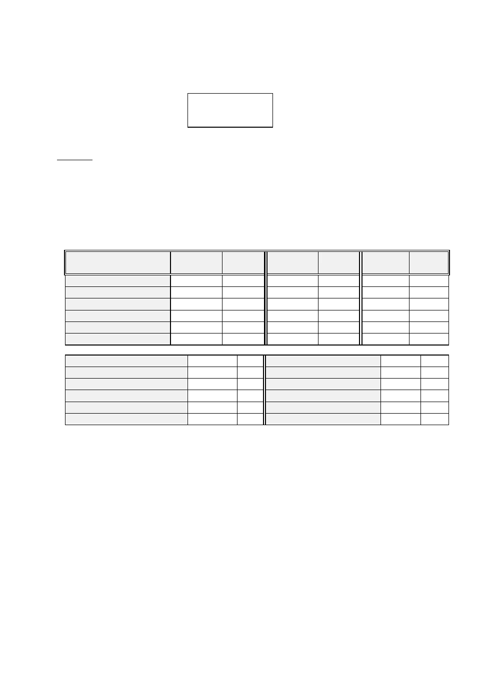
Each display has two digits to select the desired parameters among the ones in the
attached code chart:
Parameter
Symbol
phase L1
Code
Symbol
phase L2
Code
Symbol
phase L3
Code
Single voltage
V 1
01
V 2
07
V 3
13
Current
A 1
02
A 2
08
A 3
14
Active power
kW 1
03
kW 2
09
kW 3
15
Inductive power
kvarL 1
04
kvarL 2
10
kvarL 3
16
Capacitiva power
kvarC 1
05
kvarC 2
11
kvarC 3
17
Power factor
PF 1
06
PF 2
12
PF 3
18
Three phase single voltage Vav III
19
Frequency
Hz
25
Three phase current
Aav III
20
Three ph. apparent power kVA III
26
Three phase active power kW III
21
Ph-Ph voltage L1- L2
V 12
27
Three. ph. inductive power. kvarL III
22
Ph-Ph voltage L2 - L3
V 23
28
Three ph. capacitive power
kvarC III
23
Ph-Ph voltage L3 - L1
V 31
29
Three ph. power factor.
PF III
24
Three ph. Ph-Ph voltage
Vc III
30