L1 l2 l3, Thd pf, Pd kvvar =h hz – CIRCUTOR CVM-MINI Series User Manual
Page 7: 3 operating mode, 2 connection diagrams, Page 7 of 26, Cl] onil o?l
Page 7 of 26
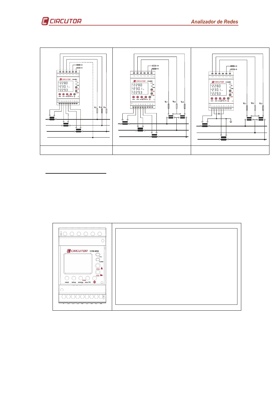
2.2.2 Connection diagrams
S2
P2
S1
P1
L1
L2
L3
N
S2
P2
S1
P1
S2
P2
S1
P1
N
A
lim
e
n
ta
c
io
n
P
o
w
e
r
S
u
p
p
ly
S2
P2
S1
P1
L1
L2
L3
S2
P2
S1
P1
S2
P2
S1
P1
b
B
a
A
b
B
a
A
L1
L2
L3
b
B
a
A
b
B
a
A
S2
P2
S1
P1
S2
P2
S1
P1
A
lim
e
n
ta
c
io
n
P
o
w
e
r
S
u
p
p
ly
Figure 2. [4-wire / 3-wire - Low Voltage]
Figure 3. [2 voltage transformers -
3 current transformers]
Figure 4. [2 voltage transformers -
2 current transformers]
3 OPERATING MODE
When power is supplied to the CVM-MINI, the equipment will start its software interface
on the screen showing the version of the firmware and its setting. After a few seconds
the equipment is ready to operate and shows all available screens.
Once started the power analyzer will display the programmable electrical parameters
via the measurement Set-up. If there is no previous setting, the analyzer will display the
voltage between phase and neutral for L1, L12 and L1
=cl]
onil
O?L+(**
Figure 5. CVM-MINI
'
'
'
2(2(2(2
2(2(2(2
2(2(2(2(22
L1
L2
L3
THD
PF
OS
C
I
N
Pd
kvVAr
=h
Hz
Figure 6. CVM-MINI display - LCD SEGMENTS