2 start-up – CIRCUTOR CVM-MINI Series User Manual
Page 6
Page 6 of 26
2.1.6 Operating conditions
Operating temperature:
-10 ºC / +50ºC
Relative humidity:
5 to 95 % RH (without condensation)
Altitude:
Up to 2000 metres
2.1.7 Safety
Designed for category III installations, 300 V
∼ AC (EN 61010).
Class II double insulation against electric shock protection.
2.2 Start-up
The equipment is mounted on a DIN rail 46277 (EN 50022). All connections must
remain inside the electrical board.
Note that when the instrument is switched on, the terminals may be dangerous
when touched and opening or removing parts may access dangerous areas.
Therefore, the equipment must not be used until it is properly installed.
The equipment must be connected to a power supply circuit protected with gl (IEC 269)
or type M fuses between 0.5 and 2 A. It must have an overload/short circuit switch or
equivalent device in order to disconnect the equipment from the power supply system.
An earth leakage switch or similar device must be fitted to disconnect the equipment
from the power supply system. The power supply circuit and the voltage measurement
circuit are connected with a cable with a minimum diameter of 1 mm
2
.
The secondary line for the current transformer shall have a minimum diameter of 2.5
mm
2
.
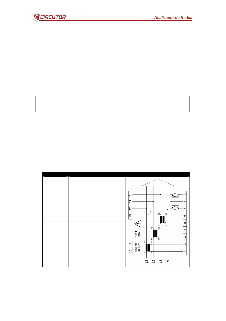
2.2.1 Description of terminals
TERMINAL TERMINAL DESCRIPTION
1
Current input AL1 - S1
2
Current input AL1 - S2
3
Current input AL2 - S1
4
Current input AL2 - S2
5
Current input AL3 - S1
6
Current input AL3 - S2
7
Transistor output RL2
8
Common transistor output
9
Transistor output RL1
10
Measurement VL3
11
Measurement VL2
12
Measurement VL1
13
Neutral V measurement
14
Power supply voltage input
15
Power supply voltage input
A
RS-485 (+)
S
RS-485 (GND)
B
RS-485 (-)