CIRCUTOR CVM-MINI Series User Manual
Page 17
Page 17 of 26
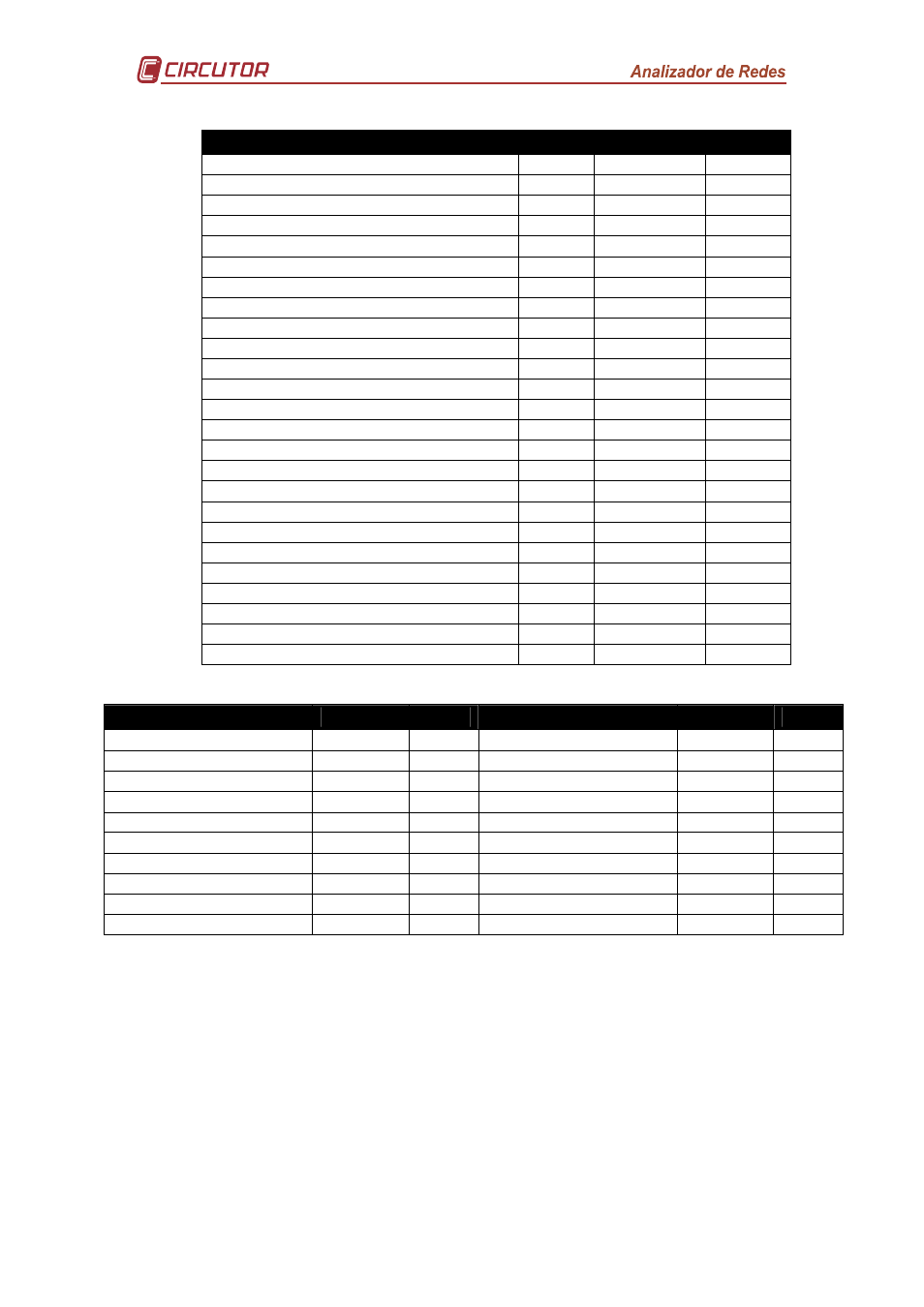
PARAMETER
PHASE SYMBOL
CODE
Phase-neutral voltage
L1
V 1
01
Current
L1
A 1
02
Active power
L1
kW 1
03
Reactive power L/C
L1
KvarL/C 1
04
Apparent power
L1
kV·A
38
Power factor
L1
PF 1
05
% THD V
L1
THD V1
25
% THD A
L1
THD A1
28
Phase-neutral voltage
L2
V 2
06
Current
L2
A 2
07
Active power
L2
kW 2
08
Reactive power L/C
L2
KvarL/C 2
09
Apparent power
L2
kV·A
39
Power factor
L2
PF 2
10
% THD V
L2
THD V2
26
% THD A
L2
THD A2
29
Phase-neutral voltage
L3
V 3
11
Current
L3
A 3
12
Active power
L3
kW 3
13
Reactive power L/C
L3
KvarL/C 3
14
Apparent power
L3
kV·A
40
Power factor
L3
PF 3
15
% THD V
L3
THD V3
27
% THD A
L3
THD A3
30
Temperature
-
ºC
41
PARAMETER
SYMBOL
CODE PARAMETER
SYMBOL
CODE
Active power III
kW III
16
cos
ϕ three-phase
cos
ϕ
19
Inductive power III
kvarL III
17
Power factor III
PF III
20
Capacitive power III
kvarC III
18
Frequency
Hz
21
Active energy
kW·h
31
L1- L2 Voltage
V 12
22
Inductive reactive energy
Kvarh·L
32
L2- L3 Voltage
V 23
23
Capacit. reactive energy
Kvarh·C
33
L3- L1 Voltage
V 31
24
Apparent power III
kV·A III
34
Temperature
ºC
41
Maximum demand
Md (Pd)
35
Maximum demand L1
Md (Pd)
35*
Current III
AIII
36
Maximum demand L2
Md (Pd)
42*
Neutral current
I
N
37
Maximum demand L3
Md (Pd)
43*
* Variables only valid if the Maximum Demand for current has been set per phase.
There are also some codes which refer to the three-phases at the same time
(Function OR). If one of these variables has been selected, the alarm will go off
when any of the three-phases, or all three at the same time, match the preset
conditions.