3 display elements and connections, Display elements and connections – AXING SKP 2-00 User Manual
Page 5
Common
SKP 2-00
© AXING AG – state of the art: 8.12.10 – Reserving change in design and type
Page 5
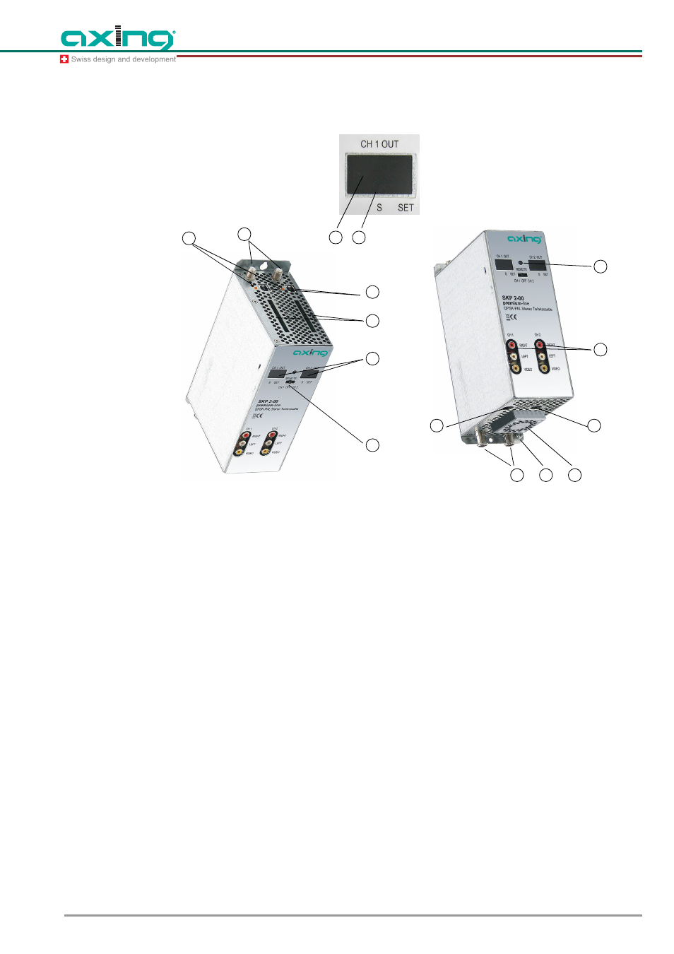
2.3 Display elements and connections
Fig. 2
Display elements and connections of the SKP 2-00
1
Programming selection switch (duct 1 – position left, duct 2 – position right). After completed pro-
gramming, the switch must be in center position!
2
Display channel number
3
Display point special channels
4
LED display MPEG data stream
Orange = MPEG data stream present, Off = MPEG data stream not present
5
SAT IF input
6
USB input for software update
7
RF output and DC input (for installation in basic unit)
8
DC input/output (only for single operation)
9
DC input/output (for the power supply of three more SKP 2-00 twin modules in single operation and
not in SKS x-xx)
10 Audio/Video outputs (cinch/RCA) for monitor connection
11 Infrared receiver
12 CI slots (to take up of CA modules)
Before installing CA modules, the power supply must be disconnected!
13 Grounding screw
14 Fan
3
2
02
6
7
8
9
10
11
12
2
1
4
5
13
14